Data numbers – KEYENCE DL-RS1A/IG User Manual
Page 13
11
Parameters of Commands and Responses
■
Data numbers
Specify the data number using three digits (ASCII characters).
●
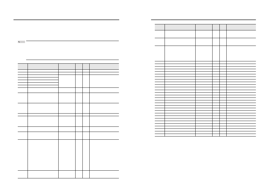
Read-only data
The following table lists the types of data that can be read from the IG Series sensor amplifiers.
• Writing read-only data results in a communication error (error number: 22).
• Reading data that cannot be set on the expansion unit results in a communication error
(error number: 22).
• When the 2 heads mode is used for the calculation function, some portion of data format
or reading range of the main unit will be changed.
Data No.
Data name
Data format
*1
No. of
bytes
Attribute
*2
Data range
033
Sensor amplifier error state*
3
*****
5
R
0 to 65535
036
Judgment output/Edge check output*
4
**
2
R
0 to 15
037
P.V. value*
5
*
6
±**.***
7
R
-99.999 to +99.999
038
R.V. value*
5
039
Peak hold value during hold period*
5
*
6
040
Bottom hold value during hold period*
5
*
6
041
Calculation Value (CALC value)*
5
*
6
042
Analog output value
±*.*** or +**.**
6
R
Analog voltage output: -5.000 to +5.000*
7
Analog current output: +04.00 to +20.00*
7
045
T connector connection sensor head
*
1
R
1: IG-028 Transmitter
2: IG-010 Transmitter
9: Detection impossible (including
non-connection)
046
R connector connection sensor head
*
1
R
1: IG-028 Receiver
2: IG-010 Receiver
9: Detection impossible (including
non-connection)
047
Number of edges
**
2
R
0 to 99*
8
048
Optical axis alignment state
*
1
R
0: Optical axis alignment NG (Optical
axis alignment indicator OFF)
1: Optical axis alignment OK (Optical
axis alignment indicator ON)
050
Abnormal setting*
9
*
1
R
0: Normal setting
1: Abnormal setting
051
Zero shift/Zero shift reset execution
result*
10
*
1
R
0: Executing
1: Normal termination
2: Execution impossible
052
Standard waveform registration request
result
*
1
R
0: Executing request
1: Normal termination
2: Standard waveform registration error
1 (light-receiving amount insufficient)
3: Standard waveform registration
error 2 (ambient light)
4: Standard waveform registration
error 3 (Combination error)
5: Receiver EEPROM error
6: Standard waveform registration
error 4 (Abnormal waveform)
7: Errors other than the above
053
Reset request result
*
1
R
0: Executing
1: Normal termination
2: Execution impossible
Point
Parameters of Commands and Responses
*1
In the Data format column, "±" indicates that the value can be either "+" or "-" and "*" signifies a
number from "0 to 9".
*2
R: Indicates that the data type can only be read from the sensor amplifiers.
054
EEPROM writing result*
11
*
1
R
0: Writing
1: Normal termination
2: Writing failure
055
Tolerance tuning/Two-point tuning
execution result
*
1
R
0: Executing request
1: Normal termination
2: Execution impossible
056
Calibration execution result*
12
*
1
R
0: Executing
1: Normal termination
2: Span value abnormal termination
3: Offset value abnormal termination
4: Span value/Offset value abnormal
termination
121
System parameter current state*
13
**
2
R
0 to 15
161
P.V. of pin diameter 1 or pin interval 1*
14
±**.***
7
R
-99.999 to +99.999
162
P.V. of pin diameter 2 or pin interval 2*
14
±**.***
7
R
-99.999 to +99.999
163
P.V. of pin diameter 3 or pin interval 3*
14
±**.***
7
R
-99.999 to +99.999
164
P.V. of pin diameter 4 or pin interval 4*
14
±**.***
7
R
-99.999 to +99.999
165
P.V. of pin diameter 5 or pin interval 5*
14
±**.***
7
R
-99.999 to +99.999
166
P.V. of pin diameter 6 or pin interval 6*
14
±**.***
7
R
-99.999 to +99.999
167
P.V. of pin diameter 7 or pin interval 7*
14
±**.***
7
R
-99.999 to +99.999
168
P.V. of pin diameter 8 or pin interval 8*
14
±**.***
7
R
-99.999 to +99.999
169
P.V. of pin diameter 9 or pin interval 9*
14
±**.***
7
R
-99.999 to +99.999
170
P.V. of pin diameter 10 or pin interval 10*
14
±**.***
7
R
-99.999 to +99.999
171
P.V. of pin diameter 11 or pin interval 11*
14
±**.***
7
R
-99.999 to +99.999
172
P.V. of pin diameter 12 or pin interval 12*
14
±**.***
7
R
-99.999 to +99.999
173
P.V. of pin diameter 13 or pin interval 13*
14
±**.***
7
R
-99.999 to +99.999
174
P.V. of pin diameter 14*
14
±**.***
7
R
-99.999 to +99.999
175
R.V. of pin diameter 1 or pin interval 1*
14
±**.***
7
R
-99.999 to +99.999
176
R.V. of pin diameter 2 or pin interval 2*
14
±**.***
7
R
-99.999 to +99.999
177
R.V. of pin diameter 3 or pin interval 3*
14
±**.***
7
R
-99.999 to +99.999
178
R.V. of pin diameter 4 or pin interval 4*
14
±**.***
7
R
-99.999 to +99.999
179
R.V. of pin diameter 5 or pin interval 5*
14
±**.***
7
R
-99.999 to +99.999
180
R.V. of pin diameter 6 or pin interval 6*
14
±**.***
7
R
-99.999 to +99.999
181
R.V. of pin diameter 7 or pin interval 7*
14
±**.***
7
R
-99.999 to +99.999
182
R.V. of pin diameter 8 or pin interval 8*
14
±**.***
7
R
-99.999 to +99.999
183
R.V. of pin diameter 9 or pin interval 9*
14
±**.***
7
R
-99.999 to +99.999
184
R.V. of pin diameter 10 or pin interval 10*
14
±**.***
7
R
-99.999 to +99.999
185
R.V. of pin diameter 11 or pin interval 11*
14
±**.***
7
R
-99.999 to +99.999
186
R.V. of pin diameter 12 or pin interval 12*
14
±**.***
7
R
-99.999 to +99.999
187
R.V. of pin diameter 13 or pin interval 13*
14
±**.***
7
R
-99.999 to +99.999
188
R.V. of pin diameter 14*
14
±**.***
7
R
-99.999 to +99.999
Data No.
Data name
Data format
*1
No. of
bytes
Attribute
*2
Data range