KEYENCE DL-RS1A/GT-70A User Manual
Page 14
12
Parameters of Commands and Responses
●
Read/write data
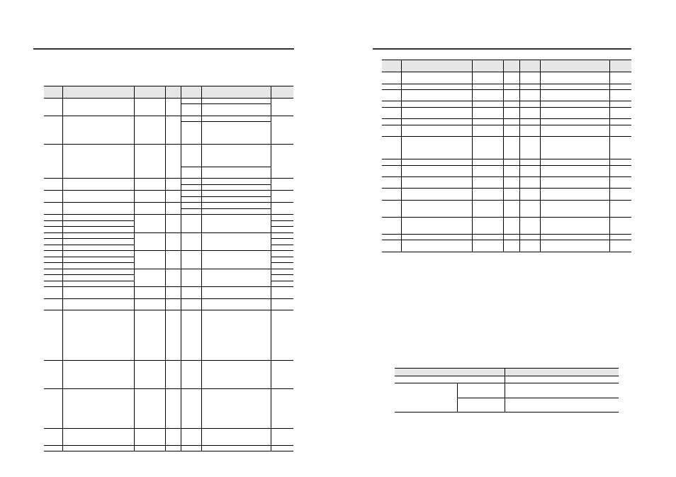
The following table lists the types of data that can be read from and written to GT-70A Series sensor
amplifiers.
Data
number
Data name
Data format
*1
Number
of bytes
Attribute
*2
Data range
Initial
value
050
Perform preset request
*
1
R
0 - 2: Last written value
1
W
0 o 1: Perform preset
*3
0 o 2: Perform preset reset
*3
051
Bank switching state
*
1
R
0 - 3: Current active bank
0
W
*4
0: Switch to bank 0
1: Switch to bank 1
2: Switch to bank 2
3: Switch to bank 3
052
Timing status
*
1
R
0: Timing input OFF or measuring
with self-timing
1: Timing input ON or not
measuring with self-timing
0
W
*5
0: Switch while measuring
1: Switch while not measuring
053
Reset request
*
1
R
0 - 1: Last written value
1
W
0 o 1: Perform reset
*3
060
Initial reset request
*
1
R
0 - 1: Last written value
1
W
0 o 1: Perform initial reset
*3
061
Core alarm error/self-timing delay
error clear request
*
1
R
0 - 1: Last written value
1
W
0 o 1: Perform error clear
*3
070
Bank 0 HIGH setting
±***.***
8
R/W
-099.999 to +999.999
+005.000
071
Bank 0 LOW setting
+002.000
072
Bank 0 preset value
+000.000
073
Bank 1 HIGH setting
±***.***
8
R/W
-099.999 to +999.999
+005.000
074
Bank 1 LOW setting
+002.000
075
Bank 1 preset value
+000.000
076
Bank 2 HIGH setting
±***.***
8
R/W
-099.999 to +999.999
+005.000
077
Bank 2 LOW setting
+002.000
078
Bank 2 preset value
+000.000
079
Bank 3 HIGH setting
±***.***
8
R/W
-099.999 to +999.999
+005.000
080
Bank 3 LOW setting
+002.000
081
Bank 3 preset value
+000.000
090
Keylock
*
1
R/W
0: Unlock
1: Lock
0
091
Bar display mode
*
1
R/W
0: Bar display mode
1: OK/NG display mode
0
100
*6*7
Calculation mode
*
1
R/W
0: OFF
1: Maximum value
2: Minimum value
3: Degree of flatness
4: Average
5: Reference difference
6: Twist
7: Warpage
8: Thickness
0
101
Detection mode
*
1
R/W
0: Standard
1: NG hold
2: Peak hold
3: Bottom hold
4: Peak-to-peak
0
102
*6
Response time
*
1
R/W
0: hsp (1.5)
1: 5 ms
2: 10 ms
3: 100 ms
4: 500 ms
5: 1000 ms
6: 5000 ms
3
103
Timing type
*
1
R/W
0: External timing input
1: Rising edge self-timing
2: Falling edge self-timing
0
104
Self-timing level
±***.***
8
R/W
-099.999 to +999.999
+000.500
Parameters of Commands and Responses
*1
In the Data format column, "±" indicates that the value can be either "+" or "-". "*" signifies a
number from "0 to 9".
*2
Indicates that the data can only be read from (R), can only be written to (W), or can be both read
from and written to (R/W) the sensor amplifiers.
*3
The command is executed only when the setting of the sensor amplifiers is changed from 0 to 1 or
from 0 to 2. To re-execute the command, you must first change the setting to 0, then change it to 1 or
2.
*4
The sensor amplifier cannot be written to in a key lock state.
*5
The sensor amplifier can only be written to if both the following conditions are met:
·
"External timing input" is selected for "Timing type".
·
"Bank B" is selected for "Input (pink/purple wire) function selection 2".
*6
When writing data numbers 100 and 102 to the sensor amplifiers using the SW command, it
takes more time to change their settings than usual. To determine the time it takes to change the
settings, add the following values to the T6 (Sensor amplifier settings change time) values
shown in "Time Frames of Communication Response Time" (page 15).
*7
The data number 100 can only be read from and written to the sensor amplifier main unit (ID
number 00).
105
Self-timing delay type
*
1
R/W
0: Static hold
1: Delay timer
0
106
User-specified delay time
****
4
R/W
0 to 9999
1000
107
Static hold delay stable determination
*
1
R/W
0: Default
1: User
0
108
Static hold delay stable range
±***.***
8
R/W
+000.000 to +999.999
+000.010
110
Measurement increase/decrease
direction
*
1
R/W
0: Normal
1: Reversed
0
111
Multiplier
***.*
5
R/W
000.1 to 100.0
001.0
112
Output mode
*
1
R/W
0: N.O.
1: N.C.
0
113
Display resolution
*
1
R/W
0: 0.001
1: 0.01
2: 0.1
3: 1
0
114
Hysteresis
±***.***
8
R/W
+000.000 to +999.999
+000.003
115
Input (purple wire) function selection
1
*
1
R/W
0: Bank A
1: Reset
0
116
Input (pink/purple wire) function
selection 2
*
1
R/W
0: Timing input
1: Bank B
0
120
Store preset value
*
1
R/W
0: YES
1: NO
0
121
Power save (eco) function
*
1
R/W
0: OFF
1: HALF
2: ALL
0
122
Core alarm
*
1
R/W
0: OFF
1: ON
2: USER
0
124
Check point setting
±***.***
8
R/W
-65.534 to +65.534
+000.500
125
Display filter function
*
1
R/W
0: ON
1: OFF
0
Written data
Value added to T6
Data number 100: Calculation mode
Sensor amplifier response time + 200 ms
Data number 102:
Response time
Calculation mode
OFF
Sensor amplifier response time
Calculation mode
ON
Sensor amplifier response time + 200 ms
Data
number
Data name
Data format
*1
Number
of bytes
Attribute
*2
Data range
Initial
value