Adjustment, Adjustment sensor head – KEYENCE LB-70(W) Series User Manual
Page 9
9
Re
d
Ye
llo
w
Gr
een
Re
d
Y
e
llo
w
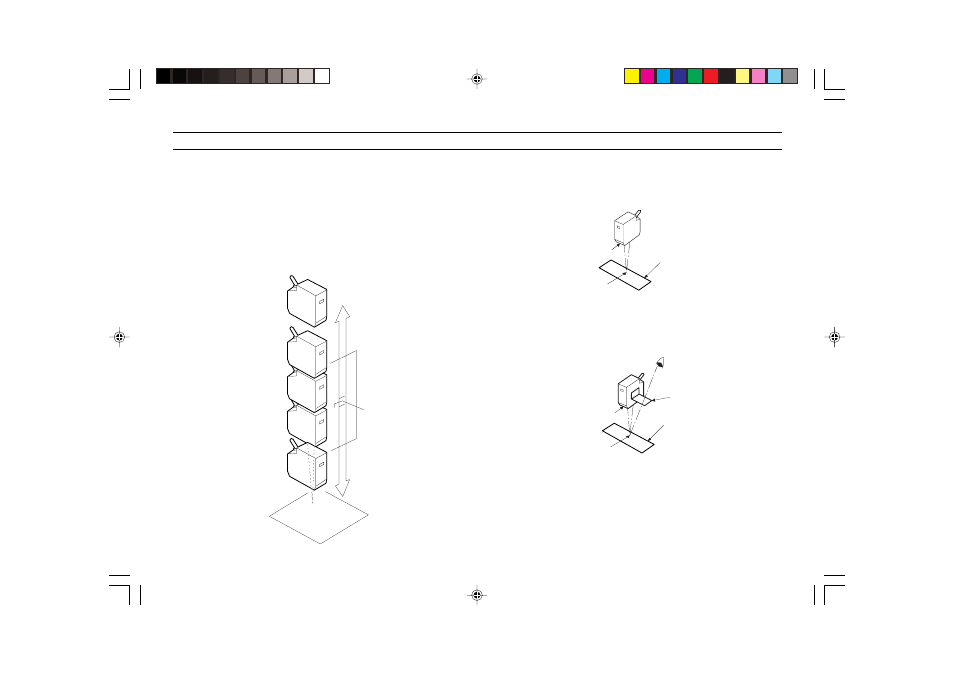
Center of
measuring
range
Measuring
range
Out of
measuring
range
Out of
measuring
range
Beam spot
Blue paper
Laser-emission
portion of
sensor head
Beam spot
Red filter
Blue paper
Laser-emission
portion of
sensor head
Visual
confirmation
ADJUSTMENT
Sensor head
1. Place the sensor head at desired location, within the range of 60 to
140 mm [LB-11(W)/70(W)] or 30 to 50 mm [LB-12(W)/72(W)] from the
target. Be sure that the laser-emitting portion of the sensor head is
parallel to the target. When the target is within the measuring range,
the STABILITY LED indicator lights yellow. When the target is at the
center of the measuring range, approximately 100 mm [LB-11(W)/
70(W)] or 40 mm [LB-11(W)/70(W)] away from the sensor head, the
STABILITY LED indicator lights green.
2. Position the supplied blue sheet of paper directly below the laser-
emitting portion of the sensor head to confirm the location of the beam
spot. Temporarily secure the sensor head at that position.
• Shut out external light in order to facilitate confirmation of beam spot.
3. After confirming the location of the beam spot, fold the supplied red
filter and affix to it the sensor head.
4. Confirm the beam spot on the paper by looking through the filter.
Tighten the mounting screws of the sensor head, then removed the
paper and filter.
• After tightening the fastening screw, remove and keep the blue paper
and the red filter.