Connections – KEYENCE LB-70(W) Series User Manual
Page 7
7
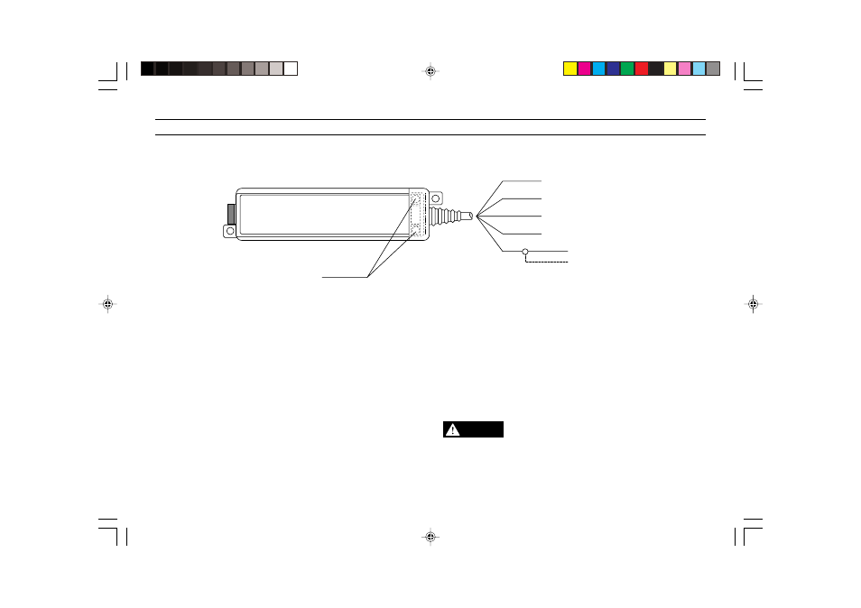
Red
Black
Yellow
Brown
Blue
12 to 24 VDC power input
0 V
Laser emission control input
Alarm output (N.C.)
Core wire
Analog voltage output
Shielded wire
Laser emission remote
control terminals
CONNECTIONS
Laser emission control input
When the yellow and black cables are short-circuited, the laser beam
stops emitting temporally.
Analog output voltage just before the short-circuitting will be freezed.
This input is used when emitting laser beams alternatively to prevent
mutual interference, or when turning off laser beams in an emergency.
Alarm output (N.C.)
The alarm output is activated when the light quantity exceeds of falls
below a specified limit.
Laser emission remote control terminals
When the terminals are short-circuited, the LASER ON alarm LED on the
front panel lights and laser emission begins after 3 seconds.
When the terminals are opened, the LASER ON alarm LED on the front
panel turns off and laser emission stops.
* For shipping purposes, a short-circuit bar is inserted between the
terminals.
The black 0 V and shielded wire have a different electrical potential.
To avoid a malfunction due to excessive noise interference, do not
connect these two wires together.
CAUTION