Error displays and corrective actions, Troubleshooting, I/o circuit diagram – KEYENCE GV Series User Manual
Page 9: Output circuit, Input circuit, Setting the shift target value, Distance display setting, Eco display setting
9
GV-IM-E
9. Setting the shift target value
Set this value to shift the current value by another amount.
•
Press the [Up] and [Down] arrow buttons simultaneously to shift the current
value to the set value with the shift target value.
The shift status is retained even if the power is turned off.
Press the [Up] and [Down] arrow buttons simultaneously and
hold them to clear the shifted target value.
•
The amplifier does not retain the amount of shift when shifting with external
input. (It is cleared when the power is turned off.) To retain the amount of
shift, press the [Up] and [Down] arrow buttons simultaneously and perform
shift.
•
When performing reference surface calibration while edge hold mode (A-1
mode) is set, the value is always shifted to 0.
•
Shift is only a effective on the selected bank.
10. Distance display setting
Sets whether to use the side close to the sensor head as the positive direction
(normal) or negative direction (reverse).
11. Eco display setting
Set this parameter to reduce the consumption current or to stop displaying
specific values. When running in power saving (eco) mode, pressing any button
returns the sensor to normal operations.
The main screen switches to eco mode if no operations take place for 30
seconds.
Output circuit
GV-21/22 (NPN output)
* GV-21 only
GV-21P/22P (PNP output)
* GV-21P only
Power is supplied to the expansion unit GV-22(P) from the expansion connector on
the back of the main unit GV-21(P). The power wires (brown and blue) of the main
unit and those of the expansion unit are common inside through the connector.
Input circuit
GV-21/22 (NPN output)
* GV-21 only
GV-21P/22P (PNP output)
* GV-21P only
Purple line. . . . . . . Laser emission stop input
Pink line . . . . . . . . External input function
*
* The external input function can be set to one of the following.
•
Not used
•
Shift
input
•
Bank switching input
•
Timing
input
Item
Setting range
Default value
Shift target
value
-199 to 999
0
Setting item
Description
Default value
nor (Normal)
The display value increases as the target
comes closer to the sensor head.
{
rEv (Reverse)
The display value decreases as the target
comes closer to the sensor head.
Setting item
Description
Default value
oFF
Turns off the eco display.
{
bAr
Turns off the digital display.
on
The digital display (green) flashes in
sequence. Bar display and channel No.
indicators are turned off.
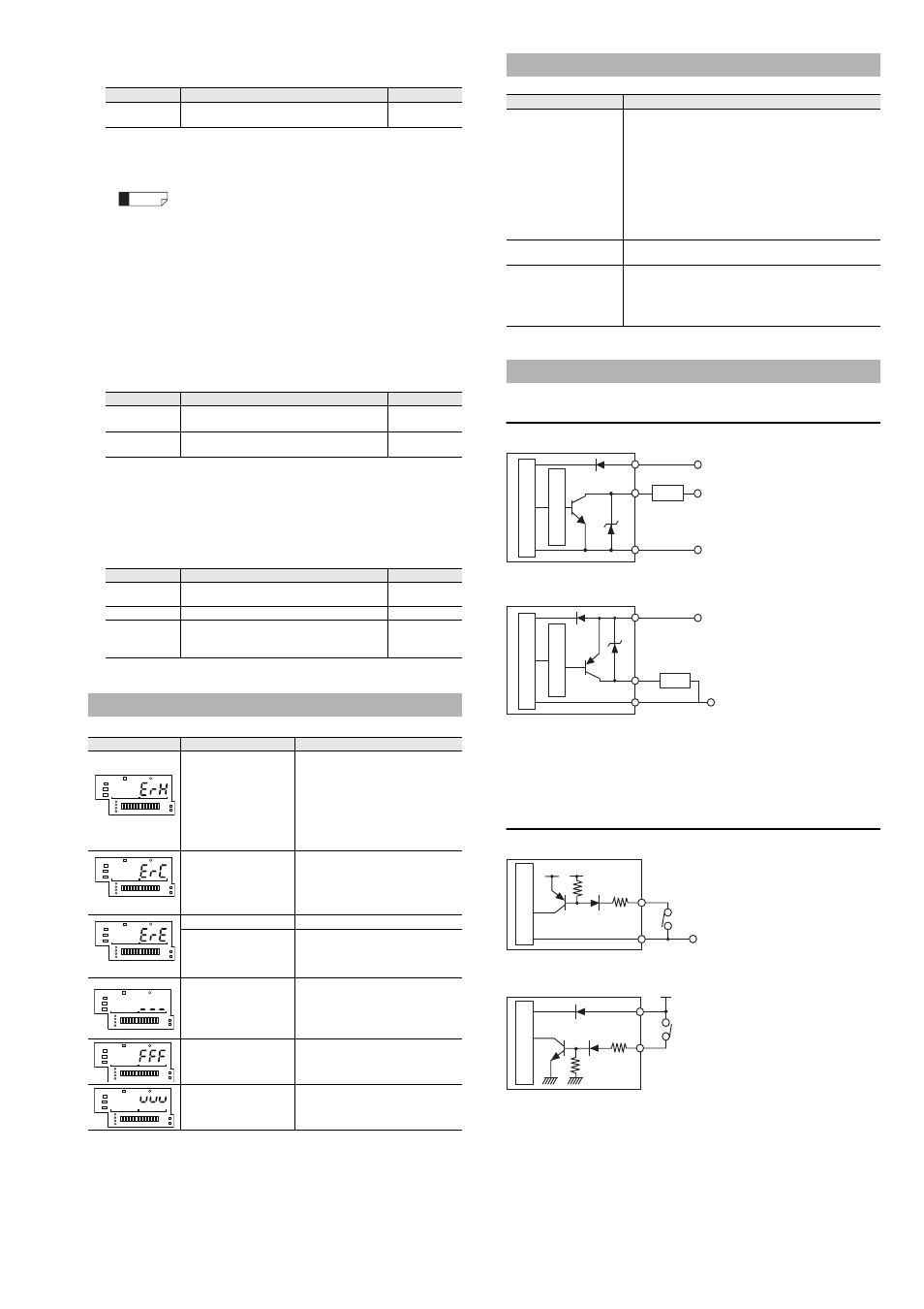
Error Displays and Corrective Actions
Error indication
Error contents
Remedy
Head error
Sensor head is not
connected.
Head cable is broken.
Sensor head is
damaged
•
Check that the sensor head is
connected.
•
Check that the head cable is not
broken.
•
Check the connection of the
head cable to the connector.
•
After checking these points, turn
on the power again.
Overcurrent error
Overcurrent is flowing
through the output wire
•
Check the load and reduce the
current to be within the rated
range.
•
Check that the output wire does not
touch another wire or a frame.
EEPROM error
Data read/write error
Perform initialization.
Data has been written in
the EEPROM over 1
million times and can no
longer be updated.
If you need to write more data,
replace the amplifier unit.
There is no workpiece
or background within
the detection distance
range, or no light is
entering the receiver.
Set a workpiece or background in
the distance for detection from the
sensor.
Reading exceeds the
detection distance
range.
Set a workpiece or background in
the distance for detection from the
sensor.
Light intensity is
saturated.
Tilt the sensor head so that specular
reflection does not enter the sensor.
Reference
1
2
1
2
1
2
1
2
1
2
1
2
Troubleshooting
Problem
Cause and solutions
The current value is
larger than the setting
value, but the output is
not reversed.
This type of problem sometimes occurs when multiple
reflection occurs while using the distance detecting
method. If this problem occurs, use the reference
surface detection (DATUM) method and configure the
sensitivity setting.
If multiple reflection occurs, the spot reflection (1spot)
indicator turns off.
•
"Distance detection method (Normal)" (page 4)
•
"Reference surface detection (DATUM) method
•
"Sensor amplifier part names" (page 3)
The external input does
not function.
Check the settings for the external input.
•
"8. External input function setting" (page 8)
The current settings can
no longer be
determined. The user
wants to return the unit
to the factory defaults.
Perform initial reset (initialization).
•
"Initial reset (initialization) and custom save function"
I/O Circuit Diagram
5-40 V DC
10-30 V DC
Load
Black/white (control output 1/2)
Brown *
Blue *
Sensor main circuit
Ov
ercurrent protection circuit
0 V
10-30 V DC
Load
Black/white (control output 1/2)
Brown *
Blue *
Sensor main circuit
Ov
ercurrent protection circuit
(Short-circuit current 1 mA max.)
PLC etc.
Purple/pink (input)
Sensor main circuit
Blue *
5 V DC
0 V
PLC etc.
Purple/pink (input)
Sensor main circuit
Brown *
10-30 V DC