Sensor amplifier, Sensor amplifier part names, Main screen – KEYENCE GV Series User Manual
Page 3
3
GV-IM-E
Sensor amplifier part names
*1
The reference surface (DATUM) detection indicator lights up when
performing reference surface detection. For more information, see
"Reference surface detection (DATUM) method (Application)" on page 5
of this Instruction Manual.
*2
The spot reflection indicator lights up during normal detection and turns off
during multiple reflection (when multiple peaks of received light intensity
occurs due to diffuse reflection), insufficient light intensity, and when the
target is out of the detection range.
*3
For more information about the CLP (clamp) function indicator, see "4.
Clamp function setting" on page 8 of this Instruction Manual.
*4
For more information about the timing input indicator, see "8. External
input setting" on page 8 of this Instruction Manual.
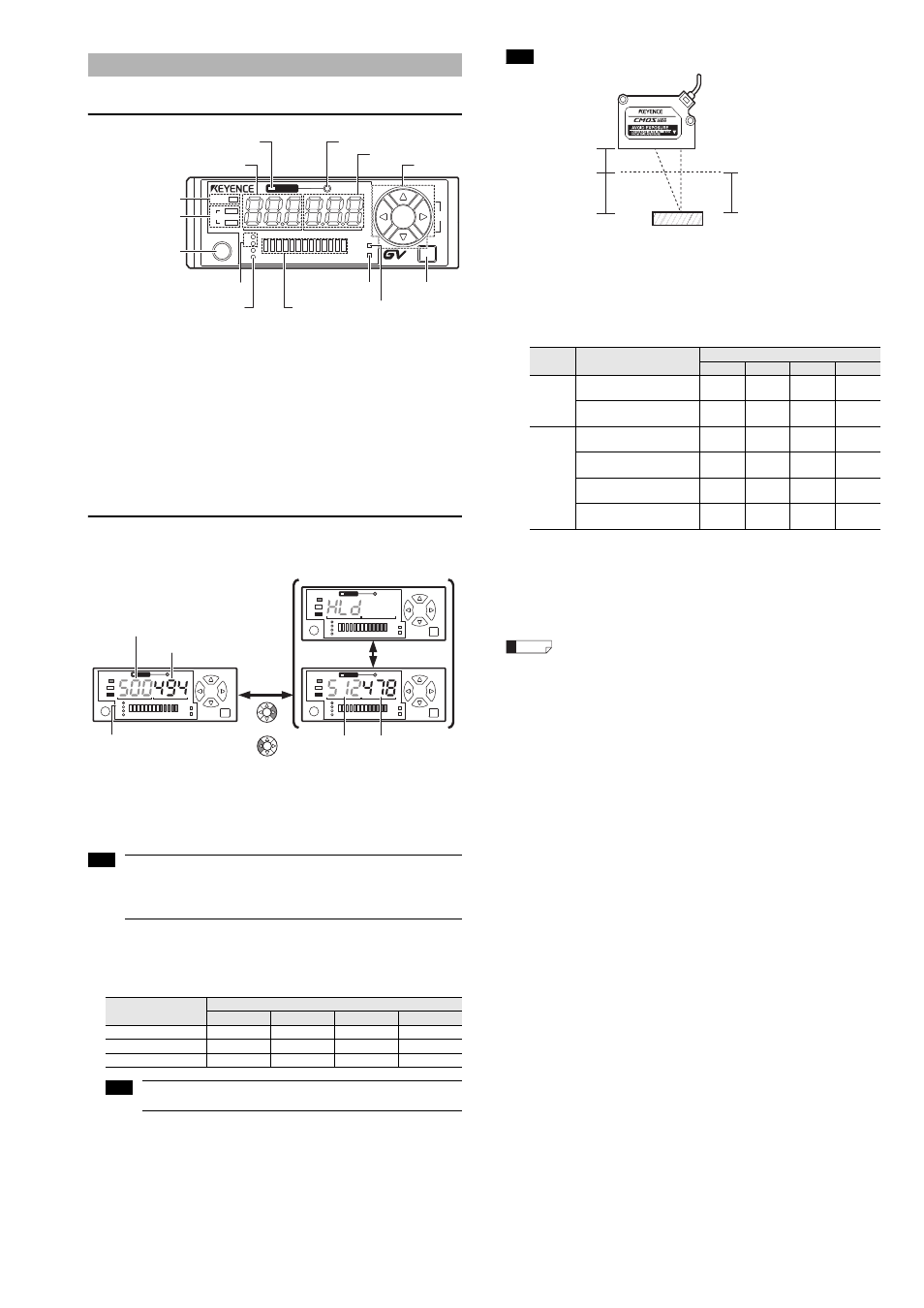
Main screen
The main screen can be switched between "Current/setting value display" and
"Peak/bottom value display". The main screen can be switched even during
keylock.
Pressing the [Up] and [Down] arrow buttons simultaneously on the main screen
forces the current value (red) to 0
*
.
* With the default settings. For details, see "9. Shift target value setting" on page 9
of this Instruction Manual.
When the channel No. 1 indicator is lit, the control output 1 (black line)
setting value is displayed. When the channel No. 2 indicator is lit, the
control output 2 (white line) setting value is displayed.
Operations are different in F-2 mode. (See page 5 of this Instruction
Manual.)
z
Current value and display resolution
In the default state, the current value shows 0 when the workpiece is located at
the maximum detection distance. Bringing the workpiece closer to the sensor
head gradually increases the value and displays it up to the minimum detection
distance.
The displayed values indicate guidelines for distances and should not
be used in the actual applications for measurement.
When using sensor head GV-H130
For example, when using the defaults with the setting value (green) at 500, the
comparator output turns on when the current value is 500 or greater and turns off
when it is less than 500.
If multiple reflection (when multiple peaks of received light intensity occurs due to
diffuse reflection) occurs during F-1, F-2, or A-1 modes, the value immediately
before the current value is held.
z
Setting value
The following table shows the default setting values for each channel.
z
Peak/bottom values
Peak value
:
Resets when the detection value exceeds the setting value
and holds the maximum value (peak value) until the
detection value falls below the setting value again.
Bottom value
:
Resets when the detection value falls below the setting value
and holds the minimum value (bottom value) until the
detection value exceeds the setting value again.
The held peak and bottom values can be cleared by pressing and hold
the [Up] arrow button.
Sensor Amplifier
Item
Current value
GV-H45 (L) GV-H130 (L) GV-H450 (L) GV-H1000 (L)
Detecting range (mm) 20.0 to 45.0 55.0 to 130.0
160 to 450
200 to 1000
Digital display (initial)
250 to 0
750 to 0
290 to 0
800 to 0
Display resolution
1
2
1
5
CLP
OUT
LASER
TIM
BANK
SET
SEL
MODE
1
2
1
2
1
spot
DATUM
series
Reference surface (DATUM) detection
indicator
*1
(red)
Current value display
(red)
Setting value display (green)
Spot reflection (1spot) indicator
*2
(green)
Arrow
buttons
Output status indicator
(red)
Laser radiation emission
indicator (green)
[SET] button
Channel No. indicator (green)
LED bar
CLP function indicator
*3
(red)
[MODE] button
Bank input indicator (green)
Timing input indicator
*4
(red)
DATUM
DATUM
DATUM
Setting value/current value display
Setting value (green)
Peak value (green) Bottom value (red)
Channel No. indicators
Current value (red)
Pressing the [MODE] button switches
the channels (channel No. indicators).
Peak value/bottom value display
Pressing the [UP] arrow button
resets the peak and bottom values.
Alternate
1
2
1
2
1
2
or
SET
MODE
SET
MODE
SET
MODE
Note
Note
Operation
mode
Item
Default value
GV-H45 (L)
GV-H130 (L) GV-H450 (L) GV-H1000 (L)
F-1, A-1,
A-2
Control output 1 (black)
(Channel 1 lit)
150
500
200
500
Control output 2 (white)
(Channel 2 lit)
125
400
150
400
F-2
Control output 1 (black) HIGH
(Channel 1 lit)
150
500
200
500
Control output 1 (black) LOW
(Channel 2 lit)
100
300
100
300
Control output 2 (white) HIGH
(Channel 1 flashing)
125
400
150
400
Control output 2 (white) LOW
(Channel 2 flashing)
75
200
50
200
Example
750
0
0mm
55mm
130mm
Current value
Distance
Minimum detection distance
Maximum detection distance
Reference