Point calibration (operation modes: f-1, a-1, a-2), Point area calibration (operation mode: f-2) – KEYENCE GV Series User Manual
Page 5
5
GV-IM-E
z
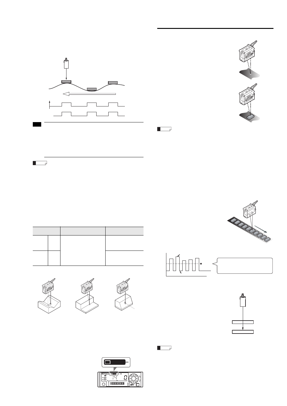
Edge hold mode (A-1 mode)
This operation mode is suitable for detecting workpieces on a conveyer or
detecting workpieces with waving backgrounds. It ignores slow distance
changes and only detects workpieces (sudden changes in height).
When height differences greater than the setting value are detected (low areas
become high), the value at the detected time are held and displayed, and
control output starts.
If the difference is small and does not exceed the setting value, the display stays as 0.
When height differences greater than the setting value are detected (high areas
become low), detection value becomes 0 and control output is stopped.
• When edge hold mode (A-1 mode) is selected, edge hold mode only
operates on channel 1. Channel 2 operates under distance
measurement mode (F-1 mode).
• If the edges are gentle (such as spherical or tilted workpieces), this
mode may not be able to detect workpieces or may output the value
incorrectly.
• Send the workpiece past the sensor head so that the area for
detecting height differences is parallel to the sensor head. See
"When detecting uneven workpieces" (page 3).
•
When a detection value is being held, press and hold the [Up] and
[Down] arrow buttons at the same time to set the current value to 0
(regardless of the shift target value) and to turn off output. The
current value for channel 2 changes to 0 as well.
•
If the external input function is set to "SFt" and the external input
(pink line) is turned on, the control output turns off and the current
value becomes 0. (When channel 2 is selected, the current value
becomes 0 as well. Turning the laser emission stop input on and
off performs a similar action, but it only changes the current value
of the channel to 0.)
Reference surface detection (DATUM) method (Application)
This method memorizes the background (reference surface) and uses it to
perform comparator output when there is a workpiece (when the state differs
from the reference surface).
The reference surface detection (reference surface calibration) can only be
used on Channel 1 of operation mode F-1/F-2.
Use the reference surface (DATUM) detection method in the following situations:
During reference screen (DATUM) detection, the background is memorizes as
references. During the unstable situations noted above, a workpiece is judged
as present when the detected surface is different from the background.
This makes stable detection possible even when using workpieces with
unstable shapes.
The reference surface (DATUM) detection indicator lights up when using reference
surface detection after performing reference surface (DATUM) calibration.
Configuring the sensitivity setting for distance
detection method
2-point calibration (operation modes: F-1, A-1, A-2)
1
Press the [SET] button once without
a workpiece in place.
The current value without the workpiece is
read.
2
Place a workpiece in the detection
position, and quickly press the [SET]
button once again.
The setting value is calculated as the mean
value between the value obtained in step 1
and the value obtained in step 2.
This concludes 2-point calibration and the
sensor returns to the detection state.
If there is very little difference between the values obtained in Step 1 and
Step 2, then "---" flashes in the setting value display area after
calibration is complete. The setting value is still updated.
Maximum sensitivity setting (operation modes: F-1, A-1, A-2)
1
Press and hold the [SET] button for at least three seconds without a
workpiece in place.
2
Release the [SET] button when "SEt" flashes on the display.
This concludes maximum sensitivity calibration and the sensor returns to the
detection state.
Full auto calibration (operation modes: F-1, A-1, A-2)
This method performs calibration while the target is moving.
1
Press and hold the [SET] button for at
least three seconds while the target
workpiece is passing through the
detection area for the sensor.
The sensitivity is set according to the
detection value while the [SET] button is
pressed.
2
Release the [SET] button when "SEt"
flashes on the display.
This concludes calibration and the sensor
returns to the detection state.
2-point area calibration (operation mode: F-2)
1
Place a workpiece on the upper limit
that you want the sensor to detect,
and press the [SET] button once.
That upper limit becomes the HIGH setting
value.
2
Place a workpiece on the lower limit
that you want the sensor to detect,
and press the [SET] button once.
That lower limit becomes the LOW setting
value.
If there is very little difference between the values obtained in Step 1 and
Step 2, then "---" flashes in the setting value display area after
calibration is complete. The setting value is still updated.
Operation
mode
Description
Changes to the
setting value
General
F-1
Turns on control output when
the detected surfaces is not the
same as the memorized
reference surface.
The current value for the
memorized surface is forcibly
set to 0. (The display is
common for channels 1 and 2.)
The setting value can be
configured around 0.
Individual setting values
cannot be changed.
Special
F-2
The setting value can be
configured around 0.
Individual setting values
can be adjusted.
Detection
value
Control
output
ON
OFF
0
Note
Reference
Influence of diffuse
reflection
(Multiple reflection)
Split spot
(Multiple reflection)
Insufficient light
intensity
CLP
OUT
LASER
TIM
BANK
SET
SEL
MODE
1
2
1
2
1
spot
DATUM
DATUM
series
Reference
Detection value
Setting
value
Time
MAX
MIN
The value is set to the mean value
between the maximum and minimum
values detected while the [SET] button is
pressed down.
Upper limit
Lower limit
Reference