Specifications, Error displays and corrective actions, Hints on correct use – KEYENCE FS-V34C(P) User Manual
Page 8: Warranty, Warranty period, Warranty scope, Product applicability
8
Copyright (c) 2010 KEYENCE CORPORATION. All rights reserved.
11292E 1070-1 96M11292 Printed in Japan
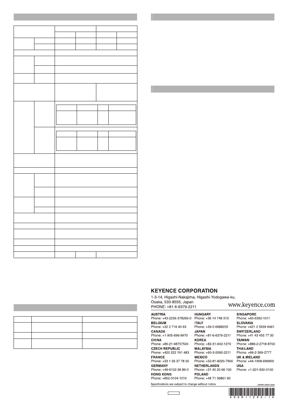
Specifications
*1
When several units are connected, the operating ambient temperature varies depending
on the number of units to be connected. When connecting several units, be sure to
mount the units on the DIN rail (mounted on a metal plate), and keep the output current
within 20 mA.
When 1 to 2 units are connected:
-10 to +55 °C,
When 3 to 10 units are connected:
-10 to +50 °C,
When 11 to 16 units are connected: -10 to +45 °C
When using the 2-output type, count one unit as two units.
*2
When double is set, the response time is twice longer. When using the 2-output type, be
careful with the number of units to be connected.
*3
When using the HIGH SPEED mode, the power consumption increases by 160 mW (7 mA).
Error Displays and Corrective Actions
Hints On Correct Use
• Do not wire the amplifier line along with power lines or high-tension lines, other-
wise the sensor may malfunction or receive damage due to noise.
• When using a commercially available switching regulator, ground the frame
ground terminal and ground terminal.
• Do not use the FS series outdoors, or in a place where extraneous light can
enter the light-receiving surface directly.
• Due to the individual dispersion of characteristics and the difference in fiber
unit model, the maximum sensing distance or displayed value of all the units
are not the same.
• If the sensor is used in S-APC mode for a long time, the LED indicators will be imposed
with a heavy load. In that case, the sensor will be automatically set to ACC mode where
the current consumption of the sensor for light emission will be constant, and “END
APC” will be displayed. The sensor can be continuously used in this case. Replace the
sensor, however, if highly precise detection is required.
WARRANTY
KEYENCE products are strictly factory-inspected. However, in the event of a failure,
contact your nearest KEYENCE office with details of the failure.
1. WARRANTY PERIOD
The warranty period shall be for one year from the date that the product has been
delivered to the location specified by the purchaser.
2. WARRANTY SCOPE
(1) If a failure attributable to KEYENCE occurs within the abovementioned warranty
period, we will repair the product, free of charge. However, the following cases shall
be excluded from the warranty scope.
• Any failure resulting from improper conditions, improper environments, improper
handling, or improper usage other than described in the instruction manual, the
user’s manual, or the specifications specifically arranged between the purchaser
and KEYENCE.
• Any failure resulting from factors other than a defect of our product, such as the
purchaser’s equipment or the design of the purchaser’s software.
• Any failure resulting from modifications or repairs carried out by any person other
than KEYENCE staff.
• Any failure that can certainly be prevented when the expendable part(s) is
maintained or replaced correctly as described in the instruction manual, the user’s
manual, etc.
• Any failure caused by a factor that cannot be foreseen at a scientific/technical
level at the time when the product has been shipped from KEYENCE.
• Any disaster such as fire, earthquake, and flood, or any other external factor, such
as abnormal voltage, for which we are not liable.
(2) The warranty scope is limited to the extent set forth in item (1), and KEYENCE
assumes no liability for any purchaser’s secondary damage (damage of equipment,
loss of opportunities, loss of profits, etc.) or any other damage resulting from a failure
of our product.
3. PRODUCT APPLICABILITY
KEYENCE products are designed and manufactured as general-purpose products
for general industries.
Therefore, our products are not intended for the applications below and are not
applicable to them. If, however, the purchaser consults with us in advance regarding
the employment of our product, understands the specifications, ratings, and
performance of the product on their own responsibility, and takes necessary safety
measures, the product may be applied. In this case, the warranty scope shall be the
same as above.
• Facilities where the product may greatly affect human life or property, such as
nuclear power plants, aviation, railroads, ships, motor vehicles, or medical
equipment
• Public utilities such as electricity, gas, or water services
• Usage outdoors, under similar conditions or in similar environments
E 1040-1
Type
Cable type
Connector type
Main unit
Sub unit
Main unit
Sub unit
Model
NPN output
FS-V33
FS-V34
FS-V33C
FS-V34C
PNP output
FS-V33P
FS-V34P
FS-V33CP
FS-V34CP
Light source
Red 4-element LED (peak wave length: 640 nm typ.)
Control
output
NPN output
NPN open collector 24 V 100 mA (2CH total) max
(2 outputs)
*1
PNP output
PNP open collector 24 V 100 mA (2CH total) max
Response time
ON/OFF
output
33 μs (HIGH SPEED)/250 μs (FINE)/500 μs (TURBO)/
1 ms (SUPER)/4 ms (ULTRA)/16 ms (MEGA)
Control input
Calibration/Scaling/
Zero-shift/Reset/Emission
stop(input time ON: 2 ms, OFF:
20 ms)
–
Number of
interference
prevention
units
Normal time
When
double is set
*2
Timer function
Timer OFF/Off-delay/On-delay/One-shot/
On-delay Off-delay/On-delay One-shot
(Timer time: 0.1 ms to 9999 ms)
Power voltage
12-24 VDC, Ripple (P-P): 10% max, Class2
Power
consumption
*3
NPN output
Normal: 710 mW max. (Using 24 V, 29 mA max., using 12 V, 40 mA max.)
Power saving: 540 mW max. (Using 24 V, 22 mA max., using 12 V, 28 mA
max.)
PNP output
830 mW max. (Using 24 V, 35 mA max., using 12 V, 45 mA max.)/
Power saving 660 mW max. (Using 24 V, 27 mA max., using 12 V, 32 mA max.)
Operating
ambient
luminance
Incandescent
lamp
20,000 lx max.
Sun light
30,000 lx max.
Operating ambient tempera-
ture
-10 to +55 °C (No freezing)
Operating ambient humidity
35 to 85% RH (No condensation)
Vibration resistance
10 to 55 Hz Compound amplitude 1.5 mm,
2 hours for each of XYZ axes
Shock resistance
500 m/s
2
3 times for each of XYZ axes
Material
Main unit, housing material: Polycarbonate
Weight (including cable)
Approx. 80g
Approx. 70g
Approx. 22g
Error display
Cause
Corrective action
'T=
Overcurrent is flowing in the control
output.
Check the load and return the current
within the rated value.
'T'
Failed to write/read the internal data.
Perform initialization (p.2).
'PF#2=
The load on the light source is large.
If highly precise detection is required,
replace the sensor.
Power mode
HIGH SPEED
FINE
TURBO/SUPER/ULTRA/MEGA
Number of units
required to pre-
vent interference
0 units
4 units
8 units
Power mode
HIGH SPEED
FINE
TURBO/SUPER/ULTRA/MEGA
Number of units
required to pre-
vent interference
0 units
8 units
16 units