Connecting fiber unit, External input, Making sensitivity settings – KEYENCE FS-V34C(P) User Manual
Page 2: Fine-adjusting sensitivity
2
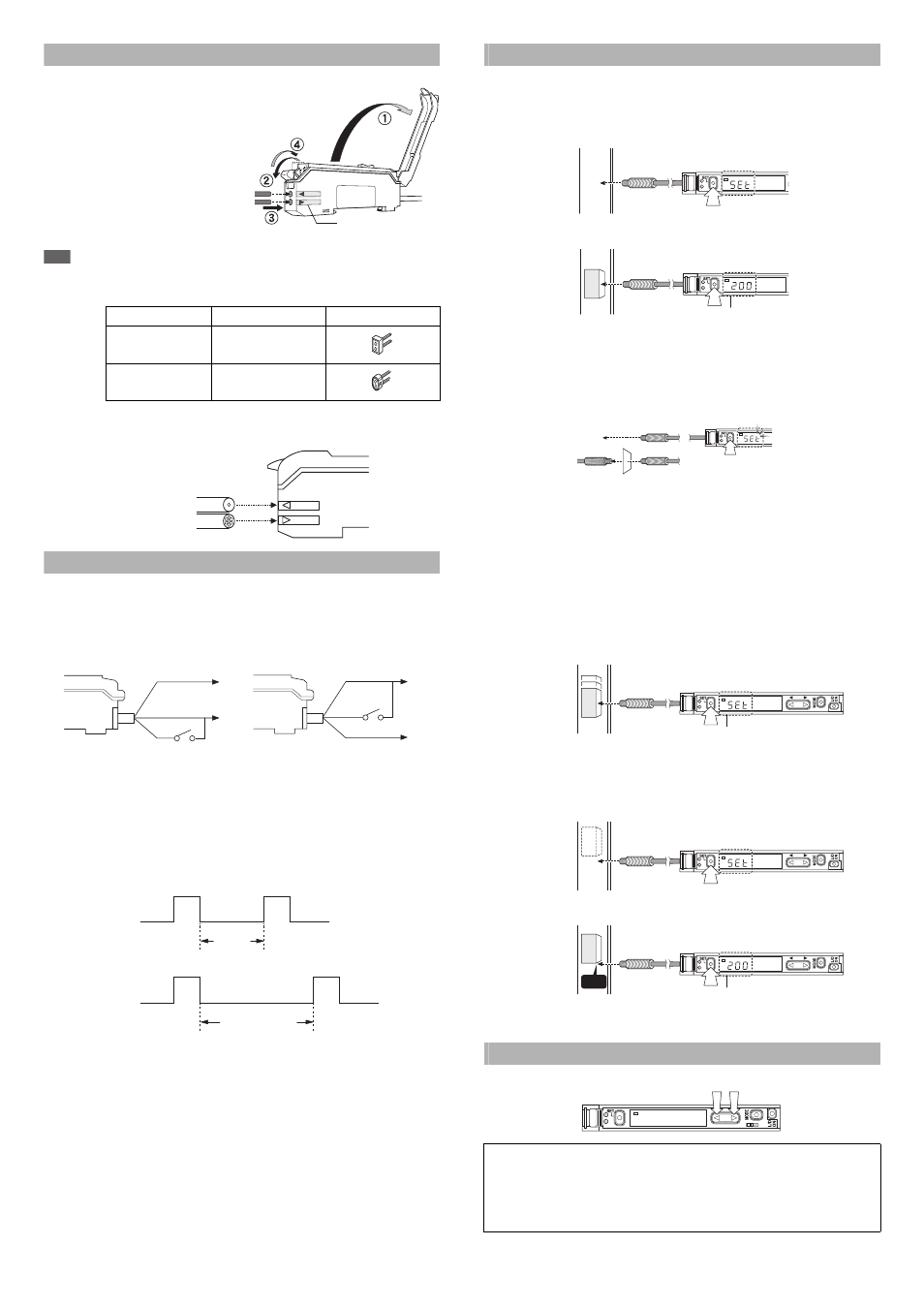
Connecting Fiber Unit
1
Open the dust cover in the
direction shown by arrow 1.
2
Move down the fiber lock lever in the
direction shown by arrow 2.
3
Insert a fiber unit into the fiber insertion holes
to a length of the fiber insertion sign (i.e.,
approximately 14 mm).
4
Move down the fiber lock lever in the
direction shown by arrow 4.
Note
If a thin fiber unit is used, an adapter provided with the thin fiber unit will be required.
Unless the right adapter is connected, the thin fiber unit will not detect targets correctly. (The
adapter is supplied with the fiber unit.)
• To connect the coaxial reflective type fiber unit to the amplifier, connect the sin-
gle-core fiber to the transmitter side, and connect the multiple-core fiber to the
receiver side.
External Input
1
Signals can be input externally by selecting an external input function (page 5, No. 5).
2
The signal can be accepted by short-circuiting the pink wire for 2 ms or more as
shown below for each model (20 ms for OFF).
* FS-V33/V33P only.
* Setting using an external input is up to 1 million times.
* No inputs are accepted while setting each mode.
When external calibration is selected, the operation is the same as with the SET button.
Special Function
By performing the following operation, both sensitivity setting and scaling can be per-
formed using external input.Select external calibration (page 5, No. 5) and display scaling
(page 6, No. 7).The following is the example when using the % calibration.
Making Sensitivity Settings
Two-point Calibration
In this mode, the setting value used will be the mean value of two sensing values
obtained with and without a workpiece.
1
Press the SET button without any workpiece placed in front of the fiber unit.
2
Place a workpiece placed in front of the fiber unit, and press the SET button.
If the sensitivity difference does not have enough room, “” flashes for about two seconds
after the calibration is complete. The set value is stored in memory even in that case.
Maximum Sensitivity Setting
Set the sensitivity without a workpiece in the case of the reflective model, and with a
workpiece in the case of the through-beam or retro-reflective model.
Press the SET button for three seconds in the state as shown in the above figure.
(Release the button when SET flashes.) The setting value is set slightly higher than
the received light intensity at the time of setting the sensitivity.
Full Auto Calibration
In this mode, the setting value will be set to the mean value of the maximum and
minimum incident values obtained within a certain period.
Use this mode to detect moving workpieces.
1
Press the set button for a minimum of three seconds while the target
workpiece is passing the sensing area of the fiber unit.
• While the set button is pressed, the sensitivity of the sensor will be set
according to the incident values.
• After the setting is completed, the setting value is displayed on the digital monitor.
Positioning Calibration
1
Press the SET button without any workpiece placed in front of the fiber unit.
2
Place a workpiece on the position where you want to perform positioning.
Press the SET button for 3 seconds or longer until the display flashes.
Fine-adjusting Sensitivity
The setting value can be directly changed by pressing the manual button.
Cable outer dia.
Adapter
Appearance
φ
1.3
Adapter A
(OP-26500)
φ
1.0
Adapter B
(OP-26501)
Fiber insertion sign
Transmitter
Receiver
Single-core fiber
Multi-core fiber
Brown *
Blue *
Pink
+V
0V
Brown *
Blue *
Pink
+V
0V
FS-V33/V34
FS-V33P/V34P
Input OFF
Input ON
% calibration
Display scaling
3 seconds
or less
Input OFF
Input ON
% calibration
% calibration
3 seconds or more
When extended display (page 6, No. 9) is set for the number of digits to be
displayed for the received light intensity
1
Press the manual button quickly once, and check that the setting value flashes.
2
While the setting value is flashing, change the setting value with the Manual button.
DSC
2
1
W
orkpiece
DSC
When the setting is completed,
the setting value is displayed.
2
1
DSC
2
1
3 sec or longer
Reflective
Thrubeam
DSC
2
1
W
orkpiece
When the setting is completed,
the setting value is displayed.
DSC
2
1
W
orkpiece
DSC
2
1
When the setting is completed,
the setting value is displayed.
Edge
W
orkpiece
DSC
1
2
2
1