Percentage calibration, Output selection, Dynamic sensitivity correction (dsc) function – KEYENCE FS-V34C(P) User Manual
Page 3: Edge detection mode, Area detection mode, Setting the display scaling, Zero-shift function
3
Percentage Calibration
This is a calibration method that can set the setting value by percentage with ref-
erence to the received light intensity at the time of sensitivity setting.
For example, if the target value is set to -10P, the setting value is determined 10%
lower than the received light intensity when the SET button is pressed.
1
When selecting the sensitivity setting method (page 5, No. 2), select the %
calibration, and set the target value of calibration.
2
Taking the desired light intensity as a reference (normally without a
workpiece), press the SET button.
* While the % calibration is in use, other calibrations (sensitivity setting) cannot be used.
Output Selection
Either light-ON mode or dark-ON mode is selectable.
Dynamic Sensitivity Correction (DSC) Function
DSC automatically corrects the setting value according to the changes in the
received light intensity when there is no workpiece (output OFF).
This function is effective when the light intensity difference is small when judging
whether or not there is a workpiece.
At Detection mode selection (page 5, No.4), select “Dynamic sensitivity correction
mode” beforehand.*
How to set the sensitivity is the same as in the normal mode.
The DSC indicator illuminates when the DSC function is set.
*
When Light ON is selected, the upper limit of the correctable range is twice as
much as the initial setting value.
*
The value is stored in memory even after the power is turned off.
*
The DSC indicator flashes when the light intensity during output OFF greatly
fluctuates or the L/D ON selection is inappropriate. In such a case, check the
setting again.
Edge Detection Mode
This mode detects the change in the received light intensity during a given period
of time. (Set at page 5, No. 4)
Filter Setting
Basically, leave this setting as its initial value. If the passage interval of workpieces
is too short for the unit to respond, strengthen the level and try again.
The selectable filter level differs depending on the power modes.
*HSP: HIGH SPEED
As the number becomes smaller, the filter becomes stronger, which makes the unit difficult to
respond to gradual changes in light intensity.
Making Sensitivity Settings
The sensitivity is set to maximum when the SET button is pressed quickly once.
When the setting value is too low and the unit detects objects other than the work-
piece, fine-adjust the setting value to a higher number.
Operation When Switching Outputs
Area Detection Mode
This mode is suited to detecting the received light intensity only of a certain range.
To set this mode, select the area detection mode at Detection mode selection (page 5, No.4).
Set the value so that the upper limit setting value is larger than the lower limit set-
ting value. The unit does not respond when the upper limit setting value is less
than or equal to the lower limit setting value.
How to Switch the Upper Limit Setting Value (HI) and the Lower
Limit Setting Value (LO)
When the
button is pressed, HI or LO and the setting value alternately flash.
When the MODE button is pressed while the display alternately flashes, the HI or
LO display changes. How to configure the sensitivity setting is the same as when
in the normal detection mode.
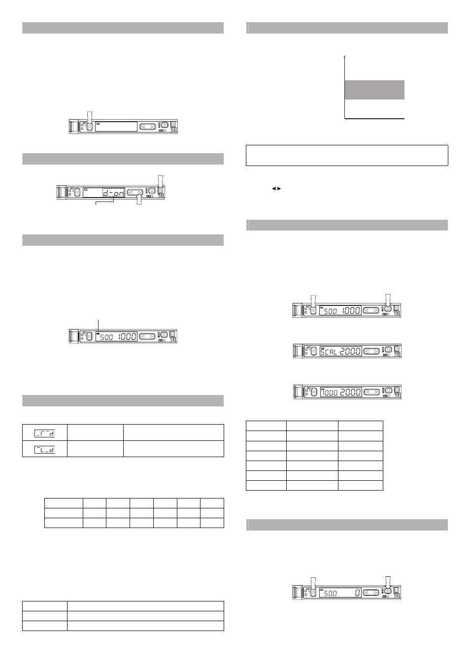
Setting the Display Scaling
This is the function to adjust the current received light intensity to the ìscaling target value.
1
When selecting a display value correction function (page 6, No. 7), select the
display scaling function, and set the target value. (The explanation here deals
with the case where the target value is set to 2000.)
2
During the normal display, press the SET button while pressing the MODE button.
(Scaling is performed for the current light intensity at this time.)
The display changes as follows, and the target value (which is 2000) to be set
as a scale is displayed.
Ø
The scaled value is displayed.
The reference light intensity can be set in the following range in reference with the
currently received light intensity:
• No value can be set when the Edge detection mode is selected.
• The value is stored in memory even after the power is turned off.
• External input can be used when using FS-V33(P)/34(P) (page 5, No.5).
Zero-shift Function
The Zero-shift function is used to forcibly set the current light intensity to zero.
1
At Display value correction function selection (page 6, No.7), select “Zero-shift function”.
2
When the SET button is pressed while the MODE button is pressed, the current
light intensity is forcibly set to zero.
• This function cannot be used when the Dynamic sensitivity correction (DSC) or
Edge detection mode is selected.
• The value is stored in memory even after the power is turned off.
• External input can be used when using FS-V33(P)/34(P) (page 5, No.5).
Rising edge detection
Detects the increase (rising edge) of the
received light intensity
Falling edge detection
Detects the decrease (falling edge) of the
received light intensity
Filter level
HSP*
FINE
TURBO
SUPER
ULTRA
MEGA
Default state
5
8
9
9
9
9
Setting range
1 to 5
4 to 8
5 to 9
6 to 9
8 to 9
9 only
Setting
Operation
L-ON
Normally OFF. Turns ON only when the light intensity changes.
D-ON
Normally ON. Turns OFF only when the light intensity changes.
DSC
1
2
2
1
Press
Press (2) within 5 seconds
after pressing (1).
(1)
(2)
1
2
2
When Area, Limit setting,
Counter, or Alarm is selected,
the selection options are
NO and NC.
DSC
1
DSC
DSC indicator
1
2
2
1
Even when the above condition is satisfied, the unit may not respond when the HI and LO values are close
to each other because of hysteresis. Be sure to operate the unit to check whether the values are valid.
Power mode
Minimum value
Maximum value
If the value exceeds the
range,
'TT
is displayed
and scaling is performed up
to the possible range.
HIGH SPEED
Approx. 1/20 times
Approx. 16 times
FINE
Approx. 1/20 times
Approx. 16 times
TURBO
Approx. 1/20 times
Approx. 16 times
SUPER
Approx. 1/40 times
Approx. 8 times
ULTRA
Approx. 1/160 times
Approx. 2 times
MEGA
Approx. 1/320 times
Approx. 1 time
HI: Upper limit setting value
LO: Lower limit setting value
ON
OFF
OFF
Received light
intensity
DSC
1
2
2
1
DSC
1
2
2
1
DSC
1
2
2
1
DSC
1
2
2
1