2inspection and adjustment 11 – Cub Cadet 7532 User Manual
Page 228
2
Inspection and Adjustment
11
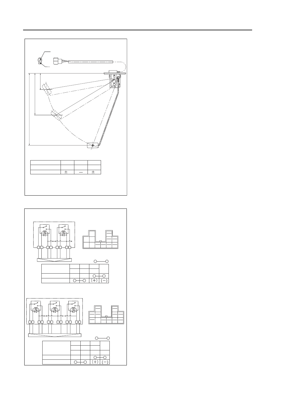
6 Fuel Gauge
Using the circuit tester, make sure that resistant value
between terminals for the fuel gauge becomes as shown
in the figure.
• If the resistant value is not as shown in the figure,
change the fuel gauge.
7 Relay
Step 1: Using the circuit tester, make sure that resistant
value between terminals for the relay becomes as shown
in the figure.
Step 2: Connect 12V to the terminal.
Using the circuit tester, make sure that resistant value
between terminals for the relay becomes as shown in the
figure.
• If the resistant value is not as shown in the figure,
change the relay.
241.7 {9.52}
138.7{5.46}
53 {2.09}
F
B
YR
E
1/2
(Unit:
Ω)
Float Position
F
3
(32.5)
110
2
7
E
1/2
Resistant Value
Tolerable
(mm {in})
GZ3W41-014
L
Y PW
GY
W
1A
1A
B
LW
L
Y
PW
GY
W
B
LW
1
2
L
Y
W
GY
LW
PW
B
HST Specification
Manual Specification
Step
Key switch
(LOAD)
1
2
L
Y
W
GY
LW
O
LG
GW
PW
B
BrB
Step
a
a
b
b
c
c
i
i
k
l
l
d
d
j
j
L
Y PW
GY
W
B
LW
a
b
c
i
O
m
LG
p
GW
n
BrB
o
l
d
j
Lamp
Key switch
(LOAD)
Lamp
IND PTO
L
Y
PW
GY
O
GW
BrB LG
W
B
LW
a b
c
i
k
l
d
j
m n
o p
Continuity:
Continuity:
GZ3W41-015