Checkline WT3-200 User Manual
Page 19
Model WT3-200 Wire Terminal Pull Tester
User’s Guide
18
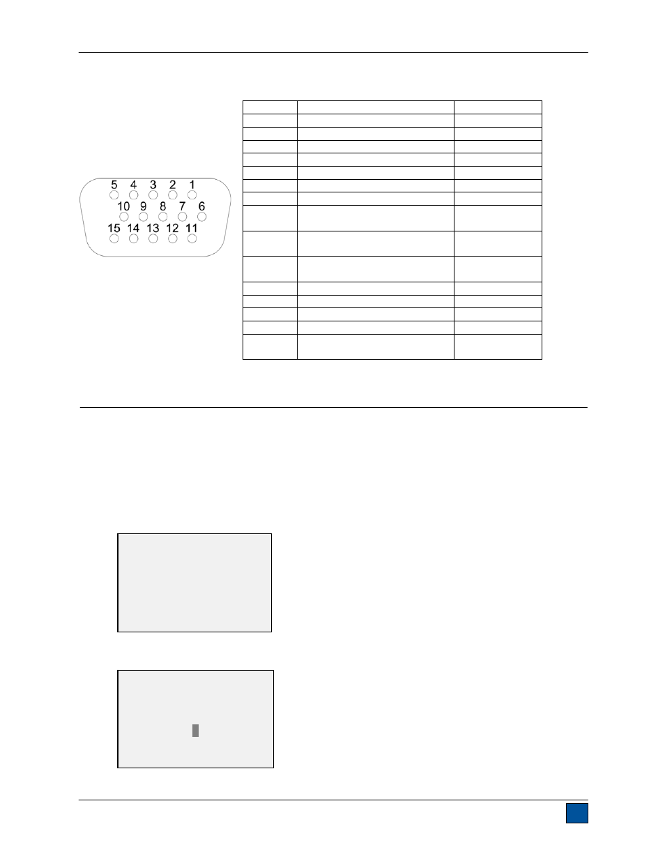
10.7 I/O Connector Pin Diagram (DB-9HD-15 female)
11 CALIBRATION
11.1 Initial Physical Setup
The tester should be mounted vertically to a test stand or fixture rugged enough to withstand a load equal
to the full capacity of the instrument. The lever mechanism should be removed. Certified deadweights or
master load cells should be used, along with appropriate mounting brackets and fixtures. Caution should
be taken while handling such equipment.
11.2 Calibration Procedure
1. Select
Calibration from the menu. The display will appear as follows:
2. Press
DIRECTION to invert the display, if desired. ENTER to continue. The display will appear as
follows:
Pin No.
Description
Input / Output
1 Signal
Ground
---
2
Tension Overload
Output
3
RS-232 Receive
Input
4 RS-232
Transmit
Output
5 +12V
DC
Output
6 Analog
Output
Output
7 Compression
Overload
Output
8 Mitutoyo
Clock
Output Bit 2
Output
9 Mitutoyo
Data
Output Bit 0
Output
10 Mitutoyo
Request
Input Bit 3
Input
11
“Under” Set Point
Output
12
“Over” Set Point
Output
13
“Within” Set Point
Output
14
Do not connect
---
15 Mitutoyo
Ready
Output Bit 1
Output
CALIBRATION
To invert the
display, press the
DIRECTION button.
THEN PRESS ENTER
CALIBRATION
ENTER # CAL POINTS
(1 TO 10)
5