2 checking the sensors, 3 running the pump, 2 checking the sensors 8.2.3 running the pump – BUCHI SpeedExtractor E-916 User Manual
Page 87
8 Troubleshooting
87
SpeedExtractor E-916/E-914 Operation Manual, Version D
8.2.2
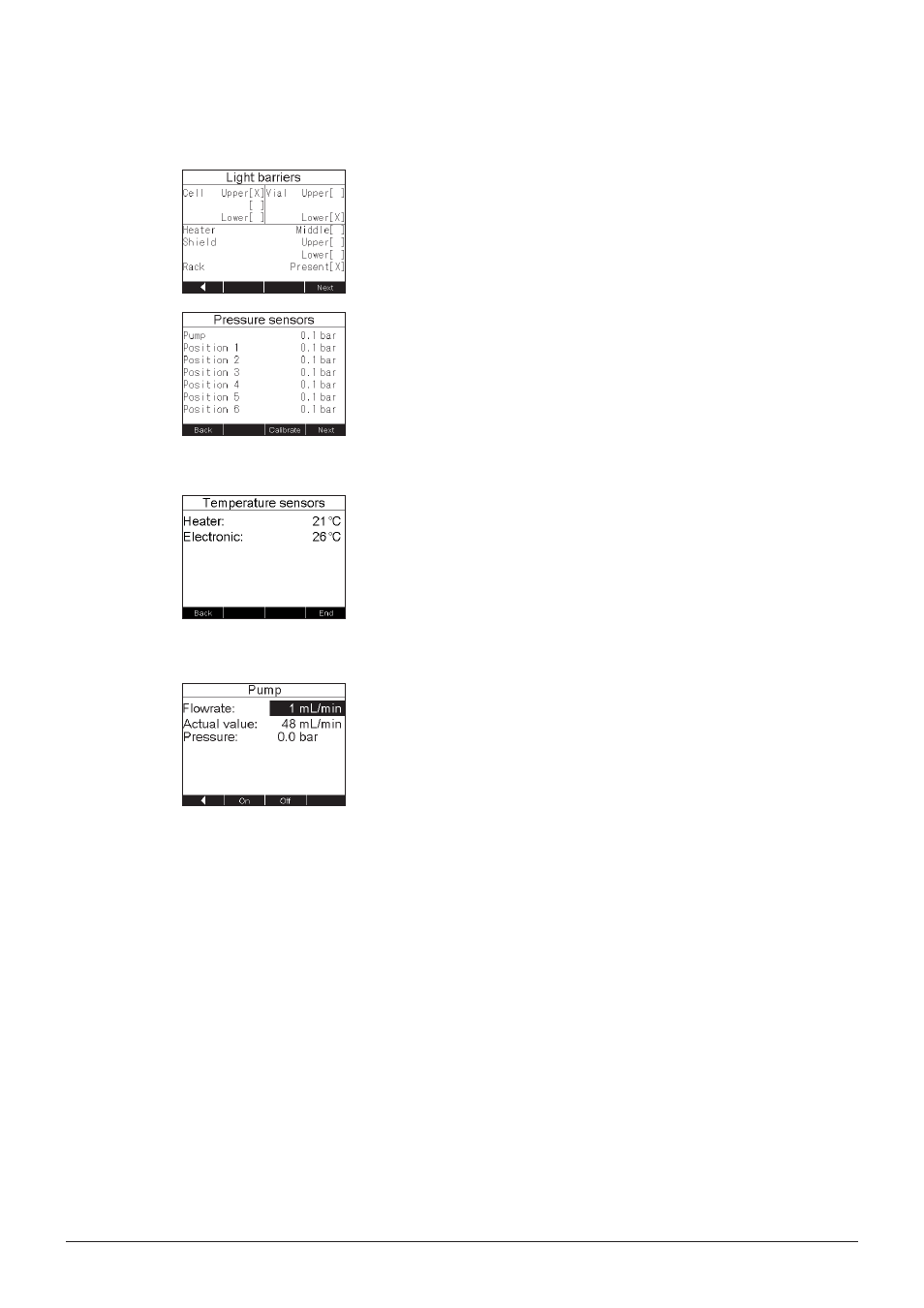
Checking the sensors
Go to SERVICE FUNCTIONS SENSORS. The position of
the lift for the heating block (CELL), the lift for the collection
rack (VIAL), the heating block (HEATER), the protection shield
(SHIELD), and the presence of the collection rack (RACK) is
shown. Crossed brackets [X] indicate the present position.
Press NEXT to enter the PRESSURE SENSORS submenu.
The overall pressure between the media valve and the divider
(indicated by PUMP; see section 4.4) and depending on the
type of instrument the pressure of the six or four position valves
is shown.
Press CALIBRATE to calibrate the pressure sensors to 0 bar.
Therefore the instrument must not be under pressure, so open
the heater and the positions valve before calibration.
Press NEXT to enter the TEMPERATURE SENSORS submenu.
The temperature is shown for the heating block and the main
board (PCB).
Press END to go back to the SERVICE FUNCTIONS.
8.2.3
Running the pump
Go to SERVICE FUNCTIONS PUMP. Enter the flow rate us-
ing the selection knob (1 – 50 mL/min). Press ON. The ACTUAL
VALUE converges to the set value. If the ACTUAL VALUE
remains 0, the pump is defective. Contact a BUCHI service
engineer.
The actual pressure is shown.
NOTE
Never run the pump dry. Never run the pump against a closed
valve. Solvent may get in the instrument when the extraction
positions are empty or the lift is not closed.
Go back to the SERVICE FUNCTIONS with the left arrow.