3 pump maintenance, 1 connections – BUCHI SpeedExtractor E-916 User Manual
Page 68
7 Maintenance
68
SpeedExtractor E-916/E-914 Operation Manual, Version D
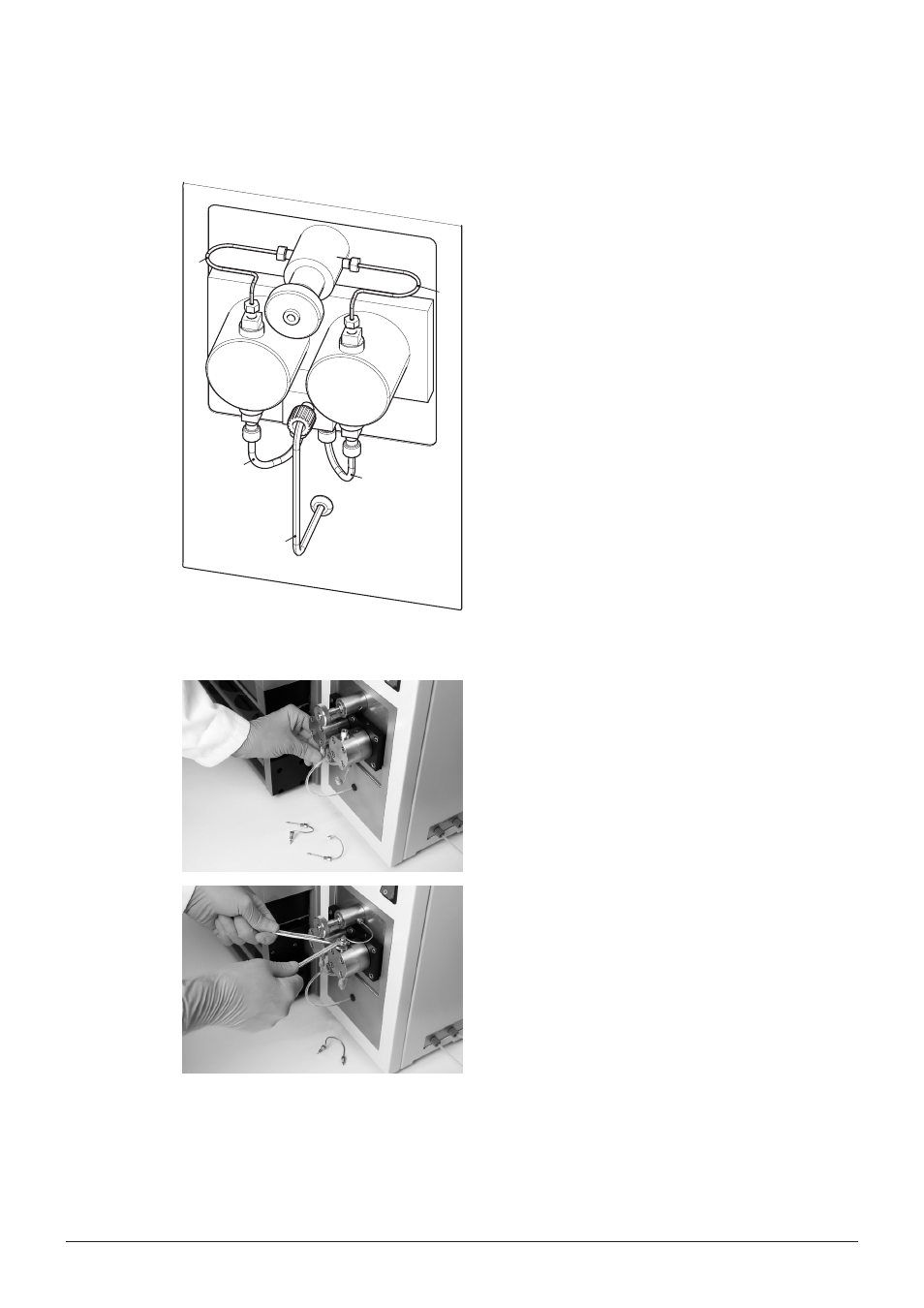
7.3
Pump maintenance
d
b
a
b
e
c
c
f
Pump designations
a Mixer outlet line
b Pump inlet lines (left, right identical)
c Pump heads
d Pump outlet capillary left
e Pump outlet capillary right
f By-pass valve
7.3.1
Connections
FEP tubings
Use FEP tubing OD 1/8”, ID 1/16” for the mixer
outlet and pump inlet lines. Make sure that the ferrule
(P/N 053664) is flush with the end of the tubing. After
the tubing has been prepared in this way, screw it into
the input block while continuously pressing the tubing
to the inside until the end of the tubing is firmly seated
on the bottom of the opening.
Outlet capillary
Unscrew the capillary from the outlet opening using a
¼” spanner wrench. Use 1/16” x 1 mm outlet capil-
laries on which a ferrule and a screw are placed left:
P/N 053613; right: P/N 053614. In contrast to the FEP
tubing, the ferrule on the metal capillary should head
out of the screw. Screw the capillary prepared in this
way into the corresponding connection using a ¼”
spanner wrench while continuously pressing the capil-
lary to the inside until the end of the capillary is firmly
seated on the bottom of the opening bottom.