Cv unit start-up – Carrier OMNIZONE 50BV020-064 User Manual
Page 31
31
when it starts. Also, no cooling will be produced at the
evaporator. If any of these conditions occurs, refer to the
Service section to correct the compressor rotation before
continuing.
INTERNAL WIRING — Check all electrical connections in
unit control boxes; tighten as required.
RETURN-AIR FILTERS — Check that correct filters are
installed in filter tracks (see Tables 3A and 3B). Do not operate
unit without return-air filters.
COMPRESSOR MOUNTING — Compressors are internal-
ly spring mounted. Do not loosen or remove compressor hold-
down bolts.
REFRIGERANT SERVICE PORTS — Each refrigerant system
has a total of 2 Schrader-type service gage ports per circuit. One
port is located on the suction line, and one on the compressor
discharge line. Be sure that caps on the ports are tight.
CV Unit Start-Up
EVAPORATOR FAN — Fan belt and variable pitch motor
pulleys are factory installed. See Tables 13-20
for fan perfor-
mance data. Be sure that fans rotate in the proper direction.
COOLING — Set the space thermostat to OFF position. Turn
on unit power. Set space thermostat to COOL and the fan to
AUTO. Adjust the thermostat temperature setting below room
temperature. Compressor 1 starts on closure of contactor (com-
pressors 1 and 2 on 4-circuit units with 2-stage thermostat).
Adjust the thermostat to an even lower setting until the ther-
mostat energizes Y2 (the second cooling stage). Compressor 2
starts on closure of contactor (compressors 3 and 4 on 4-circuit
units with 2-stage thermostat).
Adjust the thermostat temperature to a setting just below
room temperature. The second stage of cooling should turn off.
Set the thermostat temperature above room temperature. All
compressors and the unit fan should now be off.
HEATING (Heat Pump Units Only) — Follow the same se-
quence as for cooling (above), except set the space thermostat
to HEAT, and instead of adjusting the thermostat below room
temperature, adjust it above. Verify that the compressors turn
on and the unit runs in reverse cycle mode.
Set the thermostat below room temperature and confirm
that the compressors and fan turn off.
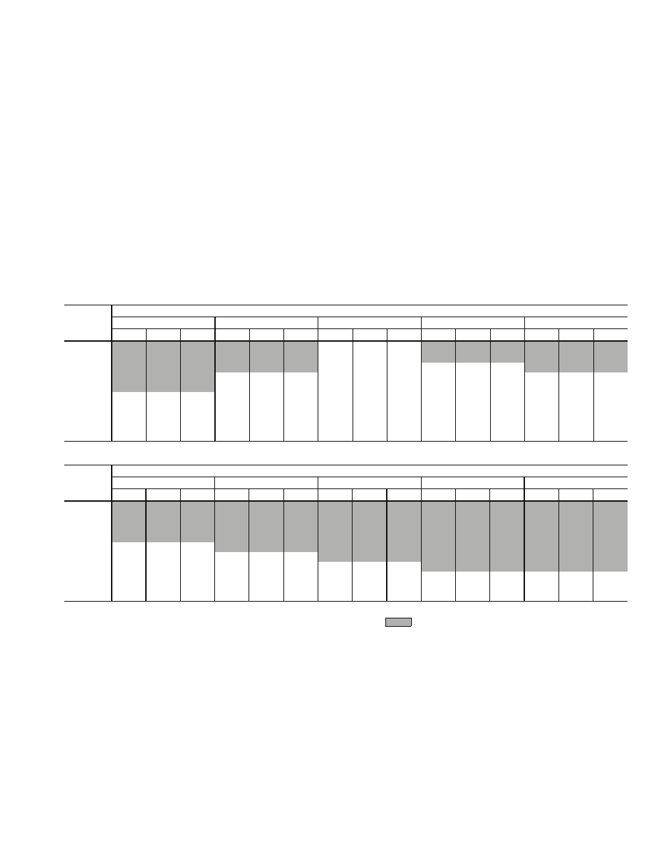
Table 13 — Fan Performance — 50BVC,E,Q020
LEGEND
NOTES:
1. Units are available with the following motor and drive combina-
tions: 1.5, 2, 3, 5 HP standard drive; 1.5, 2, 3 HP medium static
drive.
For 1.5, 2, 3 HP standard drives, the drive range is 753 to
952 rpm. For medium static drives, the drive range is 872 to
1071 rpm. For 5 HP standard drives, the drive range is 967 to
1290 rpm.
2. Italics indicates field-supplied drive required.
3.
Do not operate in shaded area.
4. Static pressure losses must be applied to external static pres-
sure before entering the fan performance table.
5. Interpolation is permitted, extrapolation is not.
6. Fan performance is based on filter, unit casing and wet coil
losses.
7. Bhp values are per fan. Watts values are per motor. Unit has
2 supply fans and 2 motors.
AIRFLOW
(cfm)
AVAILABLE EXTERNAL STATIC PRESSURE (in. wg)
0.2
0.4
0.6
0.8
1.0
Rpm
Watts
Bhp
Rpm
Watts
Bhp
Rpm
Watts
Bhp
Rpm
Watts
Bhp
Rpm
Watts
Bhp
4500
—
—
—
—
—
—
623
459
0.52
—
—
—
—
—
—
5000
—
—
—
—
—
—
638
545
0.61
—
—
—
—
—
—
5500
—
—
—
—
—
—
655
641
0.72
725
755
0.85
—
—
—
6000
—
—
—
608
641
0.72
676
755
0.85
742
878
0.99
807
1001
1.13
6500
—
—
—
636
755
0.85
699
878
0.99
761
1010
1.14
821
1142
1.29
7000
604
774
0.87
666
906
1.02
726
1029
1.16
784
1170
1.32
841
1311
1.48
7500
634
916
1.03
693
1057
1.19
750
1189
1.34
805
1330
1.50
858
1480
1.67
8000
667
1085
1.22
723
1226
1.38
777
1377
1.55
829
1526
1.72
880
1676
1.89
8500
700
1273
1.43
753
1423
1.60
804
1573
1.77
853
1732
1.95
902
1836
2.13
9000
735
1480
1.67
785
1638
1.84
833
1745
2.02
881
1908
2.21
927
2071
2.40
AIRFLOW
(cfm)
AVAILABLE EXTERNAL STATIC PRESSURE (in. wg)
1.2
1.4
1.6
1.8
2.0
Rpm
Watts
Bhp
Rpm
Watts
Bhp
Rpm
Watts
Bhp
Rpm
Watts
Bhp
Rpm
Watts
Bhp
4500
—
—
—
—
—
—
—
—
—
—
—
—
—
—
—
5000
—
—
—
—
—
—
—
—
—
—
—
—
—
—
—
5500
—
—
—
—
—
—
—
—
—
—
—
—
—
—
—
6000
—
—
—
—
—
—
—
—
—
—
—
—
—
—
—
6500
881
1283
1.44
—
—
—
—
—
—
—
—
—
—
—
—
7000
897
1451
1.63
951
1601
1.80
—
—
—
—
—
—
—
—
—
7500
911
1629
1.83
963
1727
2.00
1014
1881
2.18
—
—
—
—
—
—
8000
930
1781
2.07
979
1935
2.24
1028
2098
2.43
1076
2260
2.62
1124
2422
2.81
8500
950
1989
2.31
997
2152
2.50
1043
2323
2.69
1089
2485
2.88
1134
2697
3.09
9000
973
2233
2.59
1018
2404
2.79
1062
2576
2.99
1106
2779
3.18
1149
2960
3.39
Bhp
— Brake Horsepower Input to Supply Fan
Watts — Input Power to Supply Fan Motor