Table 5b — condenser pressure drop 50bvt,v,w units – Carrier OMNIZONE 50BV020-064 User Manual
Page 22
22
Table 5A — Condenser Pressure Drop
50BVC,J,Q Units
LEGEND
Table 5B — Condenser Pressure Drop
50BVT,V,W Units
LEGEND
Pressure and temperature ports are recommended in both
the supply and return lines for system flow balancing. These
openings should be 5 to 10 pipe diameters from the unit water
connections. For thorough mixing and temperature stabiliza-
tion, wells in the water piping should extend at least
1
/
2
pipe
diameter into the pipe. Measuring the condenser waterside
pressure drop and referring to Tables 5A and 5B can help to
properly set the water flow rate.
Improper fluid flow due to valving, piping, or improper
pump operation constitutes abuse that may result in voiding of
unit warranty. The manufacturer will not be responsible for
damages or failures resulting from improper piping design or
piping material selection.
EVAPORATOR CONDENSATE DRAIN — The condensate
drain connection is 1
1
/
4
-in. FPT and is located on the same side
of the unit as the condenser water connections. See dimension
drawings (Fig. 2-14) for exact location.
Drain lines should be pitched away from the unit with a
minimum slope of
1
/
8
-in. per foot and conform to all local and
national codes.
A trap must be installed in the condensate line to ensure free
condensate flow (units are not internally trapped). A vertical air
vent is sometimes required to avoid air pockets.
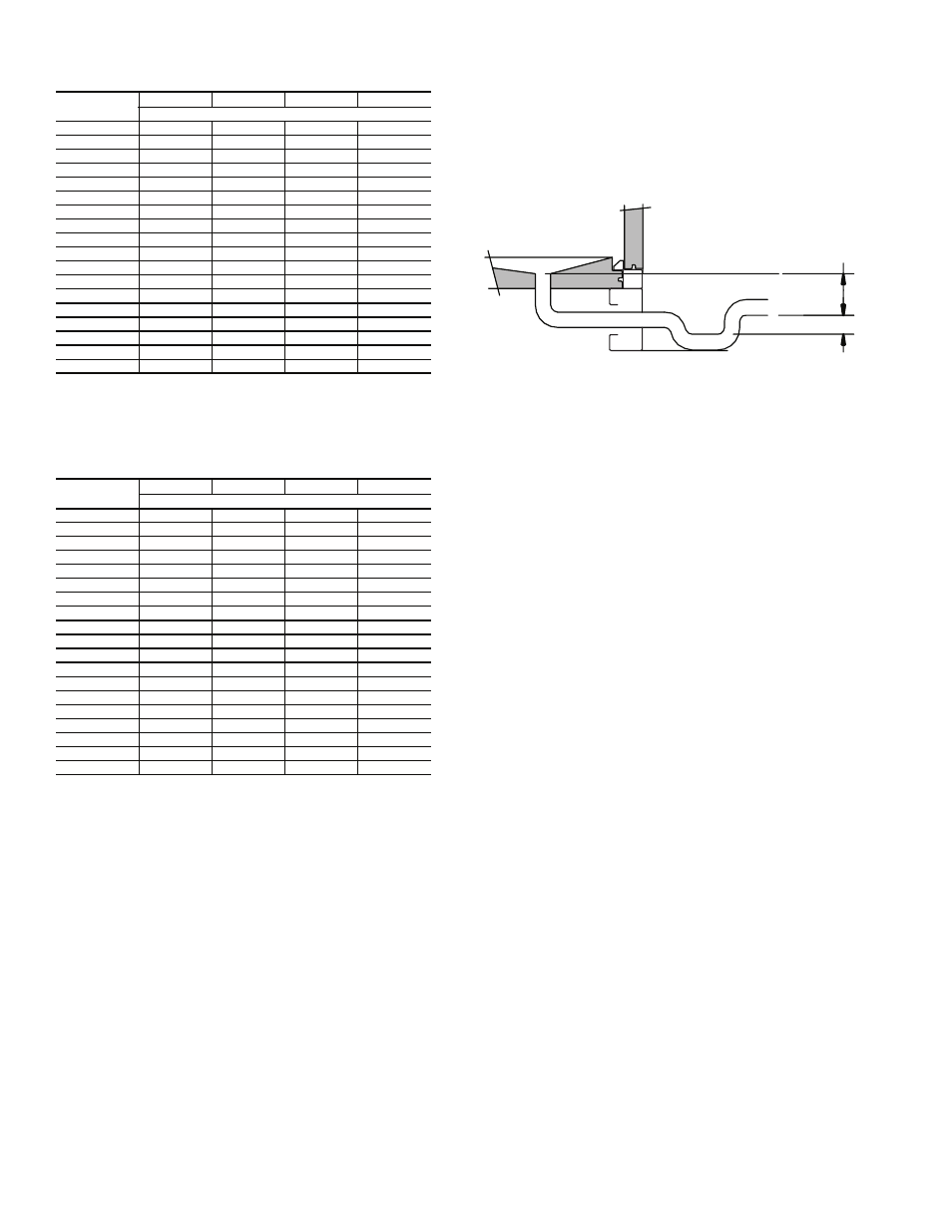
Install a condensate-trapping drain line at the units drain
connection. See Fig.
20 for correct drain layout.
When calculating trap depth, remember that it is not the
total static pressure but the upstream or downstream static
resistance that is trapped against. For instance, when calculat-
ing the trap depth for a cooling coil condensate pan, trap
against the coil pressure drop in that coil section and any other
pressure drops upstream of it.
If calculating the trap depth for the cooling coil, use the total
static pressure drop (coil plus any other components upstream
of it) plus 1 in. (P
1
= negative static pressure + 1 in.), as shown
in Fig. 21.
Traps must store enough condensate to prevent losing the
drain seal at start-up. The “Minimum
1
/
2
P
1
” dimension ensures
that enough condensate is stored.
Drain pans should be cleaned periodically to avoid the
build-up of dirt and bacterial growth.
HOT WATER HEATING COIL (Optional) — A factory-installed
one or 2-row hot water heating coil is available as an option. The
coil is supplied with hot water from a boiler through separate pip-
ing from the condenser water loop. All controls for heating opera-
tion are field-supplied.
Piping should be in accordance with accepted industry
standards and all components rated for the system pressure
expected. Pipe the coils so that they will drain, and provide a
drain and vent.
Always connect the supply to the top of the coil, and the
return to the bottom. Refer to Fig. 2-14 for hot water supply
and return piping locations.
Water coils should not be subjected to entering air tempera-
tures below 38 F to prevent coil freeze-up. If air temperatures
across the coil are going to be below this value, use a glycol or
brine solution. Use a solution with the lowest concentration
that will match the coldest air expected. Excess concentrations
will greatly reduce coil capacity.
The return air duct system should be carefully designed to
get adequate mixing of the return air and outdoor air streams to
prevent cold spots on the coil that could freeze.
A 2 or 3-way, field-supplied modulating control valve, or a
simple 2-position on-off valve may be used to control water
flow. Select the valve based on the control valve manufacturer's
recommendations for size and temperature rating. Select the
control valve CV based on pressure drop and flow rate through
the coil. This information is available from the VPACBuilder
software program or Tables 6A and 6B.
FLOW RATE
(gpm)
SIZE 020
SIZE 024
SIZE 028
SIZE 034
Pressure Drop (ft wg)
35
9.1
—
—
—
40
11.2
6.0
—
—
45
13.5
7.5
—
—
50
15.9
9.1
9.1
—
55
18.4
10.9
10.9
—
60
21.1
12.8
12.8
10.8
65
23.9
14.8
14.9
12.7
70
27.4
17.0
17.2
14.7
75
—
19.3
19.6
16.9
80
—
21.7
22.2
19.2
85
—
—
24.9
21.7
90
—
—
27.8
24.3
95
—
—
30.8
27.1
100
—
—
34.0
30.0
105
—
—
—
33.1
110
—
—
—
36.3
115
—
—
—
39.7
120
—
—
—
43.2
GPM — Flow Rate
PD
— Pressure Drop (ft wg)
FLOW RATE
(gpm)
SIZE 034
SIZE 044
SIZE 054
SIZE 064
Pressure Drop (ft wg)
60
8.7
—
—
—
70
11.9
—
—
—
80
15.5
6.3
—
—
90
19.6
8.0
—
—
100
24.2
9.9
6.0
—
110
29.3
12.0
7.3
—
120
34.9
14.3
8.7
8.7
130
—
16.7
10.2
10.2
140
—
19.4
11.8
11.8
150
—
22.3
13.6
13.6
160
—
25.3
15.5
15.5
170
—
—
17.4
17.4
180
—
—
19.6
19.6
190
—
—
21.8
21.8
200
—
—
24.2
24.2
210
—
—
—
26.6
220
—
—
—
29.2
230
—
—
—
31.9
240
—
—
—
34.8
GPM — Flow Rate
PD
— Pressure Drop (ft wg)
1/2
P
1
P
1
Fig. 20 — Condensate Drain Layout
a39-2371ef