Start-up general – Carrier OMNIZONE 50BV020-064 User Manual
Page 30
30
Table 11 — Thermistor Resistance vs Temperature
Values for Supply-Air Temperature Sensor
(10 Kilo- ohm)
SMOKE DETECTOR/FIRE ALARM SHUTDOWN
(FSD) — To allow a smoke detector to shut the 50BV down,
remove the jumper from FSD to C and wire these terminals to a
set of normally closed contacts on the smoke detector.
ALARM (ALARM) AND WARNING (WARN) OUT-
PUTS — Two dry contacts output a discrete signal when the
alarm and warning lights on the display are lit. To pick up the
alarm output signal, wire between the ALARM and ALM-CM
terminals. To pick up the warning output signal, wire between
the WARN and ALM-CM terminals.
REMOTE OCCUPANCY (ROCC) — The 50BV unit may
be commanded by another control system or a twist timer to
become occupied and run when a set of dry contacts close. In
order for this to occur, wire the contacts to ROCC and C and
set the Local/Off/Remote switch to REMOTE.
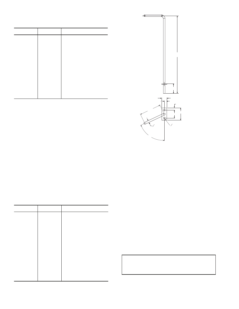
RETURN AIR TEMPERATURE SENSOR (RAS) — The
return/mixed air temperature sensor is a 5 kiloohm temperature
sensor used as the space control point. For every degree that
the RAS is below the set point, the supply air set point will be
reset by the configured value in the custom configured RESET
RATIO.
Refer to Table 12 and Fig. 31.
Table 12 — Thermistor Resistance vs Temperature
Values for Return-Air Temperature
Sensor (5 kiloohm)
Wire the sensor to PCB1 connector J3, terminals 15 and 16.
Change custom configuration as instructed in Configure the
Custom Programming Selections section. Changing this con-
figuration to YES changes the EWT input to be used as return
air temperature input.
START-UP
General —
Complete the Start-Up Checklist on page CL-1
before attempting system start-up.
CRANKCASE HEATERS — The 50BVT,U,V,W,X034-064
units include crankcase heaters. Crankcase heaters are ener-
gized as long as there is power to the unit and the compressor
is not operating.
Wait 24 hours before starting the compressors to permit
warming by the crankcase heaters.
AFTER 24 hours, continue with the procedures below.
CONFIRM THE INPUT POWER PHASE SEQUENCE —
The input power phase rotation sequence must be L1-L2-L3 =
ABC (or forward or clockwise) as indicated with a phase
rotation meter. Incorrect input phase rotation will cause the com-
pressors to rotate in reverse, which results in no cooling capacity.
If the compressor is rotating in the wrong direction, it may:
emit increased noise; shut down due to internal overload
protection; have only a small decrease in suction pressure when
it starts; or have only a small increase in discharge pressure
TEMP
TEMP
RESISTANCE
(C)
(F)
(Ohms)
–40
–40
335,651
–35
–31
242,195
–30
–22
176,683
–25
–13
130,243
–20
–4
96,974
–15
5
72,895
–10
14
55,298
–5
23
42,315
0
32
32,651
5
41
25,395
10
50
19,903
15
59
15,714
20
68
12,494
25
77
10,000
30
86
8,056
35
95
6,530
40
104
5,325
45
113
4,367
50
122
3,601
55
131
2,985
60
140
2,487
65
149
2,082
70
158
1,752
TEMP
TEMP
RESISTANCE
(C)
(F)
(Ohms)
–40
–40
167,835
–35
–31
121,098
–30
–22
88,340
–25
–13
65,121
–20
–4
48,487
–15
5
36,447
–10
14
27,648
–5
23
21,157
0
32
16,325
5
41
12,697
10
50
9,952
15
59
7,857
20
68
6,247
25
77
5,000
30
86
4,028
35
95
3,265
40
104
2,662
45
113
2,183
50
122
1,801
55
131
1,493
60
140
1,244
65
149
1,041
70
158
876
75
167
740
80
176
628
IMPORTANT: On VAV units, fan rotation direction
can NOT be used for the phase sequence check; fan
rotation for VAV units with a variable speed drive is
independent of the unit input wiring sequence.
NOTE: All dimensions are in inches.
Fig. 31 — Return Air Temperature Sensor
(P/N HH79NZ079)
a50-7274ef
1.00
8.00
0.81
1.25
0.22
0.25
0.50
2.25
65º
O0.187
O0.187
(2 HOLES)