Carrier OMNIZONE 50BV020-064 User Manual
Page 3
3
INSTALLATION
Omnizone™ 50BV units are intended for indoor installa-
tion only. Determine building alterations required to run piping,
wiring, and ductwork. Read all installation instructions before
installing the unit.
Step 1 — Complete Pre-Installation Checks
EXAMINE THE UNIT — Examine the unit for shipping
damage. File a claim with the transit company if damage is
found. Check the shipment for completeness. Verify that the
nameplate electrical requirements match the available power
supply.
UNIT STORAGE — The 50BV units are designed and pack-
aged for indoor storage and use only. If the equipment is not
needed for immediate installation upon its arrival at the job site,
it should be left in its shipping carton and stored in a clean, dry
area. Units must only be stored or moved in the normal upright
position, as indicated by the “UP” arrows on each carton, at all
times. DO NOT STACK UNITS.
MODULAR UNITS — The 50BVT,U,V,W,X units are shipped
in multiple sections for easy movement and installation. The
separate modules will pass through a standard 36-in. steel-
framed door or service elevator. Circuit integrity is maintained
because none of the refrigerant piping requires disconnection.
Water piping connections are made with the use of heavy-duty
bronze-bodied unions so no field welding or brazing is required.
See Table 2 for the number of sections per unit.
Table 2 — Modular Unit Shipping Table
NOTE: Units ship with the main air conditioning, economizer/
filter, and, when selected, the reheat coil sections assembled
together. These can be easily disassembled, as required, in the
field. The fan section(s) always ships separately.
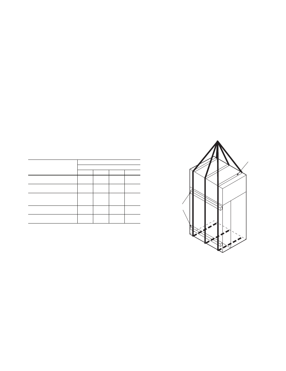
Step 2 — Rig and Place Unit —
Use proper lifting
and handling practices to avoid damage to the unit. Move
modular units with a fork truck using the baserails provided, or
use spreader bars and lifting straps as shown in Fig. 1.
For single piece units, use spreader bars and rigging straps if
lifting with a crane to avoid damage to the unit. Otherwise,
move with a fork truck using the shipping pallet.
Refer to Fig. 2-14
for unit dimensions.
Refer to Tables 3A and 3B for physical data.
REMOVE PACKAGING — Remove all protective plastic,
remove and discard unit top cover protector, filter cover,
controller display protector, and water piping connection
packaging.
UNIT LOCATION — Locate the unit in an indoor area
that allows easy removal of the filters, access panels, and
accessories. Make certain enough space is available for service
personnel to perform maintenance or repairs. Provide sufficient
room to make all water, duct, and electrical connections. If the
unit is located in a small mechanical equipment room, make
sure adequate space is available for air to return freely to the
unit. These units are not approved for outdoor installations and
must be installed inside the structure. Do not locate in areas
that are subject to freezing.
UNIT PLACEMENT — Ensure that the floor is structurally
strong enough to support the weight of the equipment with
minimum deflection. A good, level floor is required for proper
unit operation and to ensure proper fit-up and alignment of all
bolt together and union coupled modules on modular units.
SECTIONS
NUMBER OF SECTIONS
50BVT, U, V, W, X
034
044
054
064
Main Air Conditioning
Weight (lb) (each)
1
2100
2
1825
2
2200
2
2225
Reheat Coil Option
Weight (lb) (each)
1
40
2
40
2
40
2
40
Economizer/Filter
Filter Section Weight (lb)
Economizer Weight (lb)
1
310
200
2
310
200
2
310
200
2
310
200
Fan Section
Weight (lb) (each)
1
650
2
650
2
650
2
650
Total Unit
Weight (lb)
4
3300
8
5400
8
6150
8
6150
USE
SPREADER
BAR TO
PREVENT
DAMAGE
TO UNIT
4 X 4 ABOVE
AND BELOW
RETURN DUCT
CONNECTIONS
Fig. 1 — Modular Unit Rigging
a50-7257ef