Pilz PNOZ 8 110VAC 3n/o 1n/c 2so User Manual
Page 4
Die Sicherheitskontakte sind aktiviert und
der Hilfskontakt (41-42) ist geöffnet. Der
Halbleiterausgang Y32 ist durchgeschaltet.
Die Statusanzeigen "CH. 1" und "CH. 2"
leuchten. Das Gerät ist betriebsbereit.
Wird der Eingangskreis geöffnet, öffnen die
Sicherheitskontakte 13-14/23-24/33-34 ,
der Hilfskontakt 41-42 schließt. Der
Halbleiterausgang Y32 sperrt. Die Statusan-
zeige erlischt.
Wieder aktivieren:
• Eingangskreis schließen
• Bei manuellem Start zusätzlich Taster
zwischen S12 und Y1 betätigen.
Die Statusanzeigen leuchten wieder, die
Sicherheitskontakte sind geschlossen.
Zeitdifferenzverlängerung:
Bei zweikanaliger Schutztürsteuerung darf
zwischen Betätigen von Grenztaster S1 und
S2 höchstens eine Zeitdifferenz von 180 ms
liegen. Sind die Klemmen Y36-41 und Y37-
42 gebrückt, kann die Zeitdifferenz unend-
lich betragen.
(pas de pontage entre S21-S22).
Les contacts de sécurité sont fermés et le
contact d'info (41-42) est ouvert. Les LEDs
"CH. 1" et "CH. 2" sont allumées. La sortie
statique Y32 est passante. Le relais est
activé.
Si le circuit d'entrée est ouvert, les contacts
de sécurité 13-14/23-24/33-34 s'ouvrent et
le contact d'info 41-42 se ferme. La sortie
sta tique Y32 est bloquée. Les LEDs
"Channel 1" et "Channel 2" s'éteignent.
Remise en route:
• fermer le circuit d'entrée
• en cas de réarmement manuel, appuyer
sur le poussoir S12 - Y1
Les affichages d'état s'allument à nouveau.
Les contacts de sécurité sont fermées.
Temps de désynchronisme infini:
En cas de surveillance d'un protecteur
équipé de 2 interrupteurs de position, ces 2
interrup teurs doivent être actionnés
simultanément dans un intervalle detemps
qui est de 180 ms. Si les bornes Y36-41 et
Y37-42 sont pontées, cet intervalle de
temps est alors infini.
The safety contacts are activated and the
auxilliary contact (41-42) is open. The
semiconductor output Y32 is connected.
The status indicators "CH. 1" and "CH. 2"
are illuminated. The unit is ready for
operation.
If the input circuit is opened, the safety
contacts 13-14/23-24/33-34 open and the
auxilliary contact 41-42 closes. The
semiconductor output Y32 is disabled. The
status indicator goes out.
Reactivation:
• Close the input circuit.
• With manual reset, the button between
S12 - Y1 must also be pressed.
The status indicators light up again, the
safety contacts are closed.
Extending the time delay:
With two channel safety gate control the limit
switches S1 and S2 must both be activated
within a maximum of 180 ms. If the
terminals Y36 - 41 and Y37 - 42 are bridged,
this time delay can be infinite.
S11 S21
S12
Y2
Y1
S22
Y36
S52
S12 Y1
S1
S3
S11 S21
S12
S12
Y1
Y2
Y1
S22
S12
S52
S1
S3
S11 S11
S12
Y2
Y1
S52
S21
S22
Y36 Y1
S1
S3
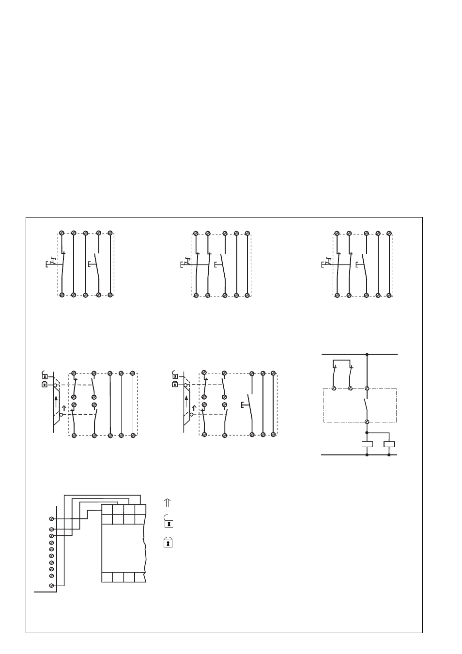
Fig. 3: Eingangskreis einkanalig: Not-Halt-
Beschaltung; manueller Start/Single
channel input: Emergency Stop wiring;
manual reset/Commande par 1 canal:
Circuit d'arrêt d'urgence, validation
manuelle
Fig. 4: Eingangskreis zweikanalig; Not-Halt-
Beschaltung; manueller Start/Two channel
input circuit: Emergency Stop wiring; manual
reset/Commande par 2 canaux: Circuit
d'arrêt d'urgence, validation manuelle
Fig. 5: Eingangskreis zweikanalig ohne
Querschlusserkennung/Two channel input
circuit; no short-circuit recognition/
Commande par 2 canaux sans détection
des c.c.
14
K4
K5
13
Y1
Y2
K4
K5
1L1
1L2
S11
S11
Y37
S22
S1
S2
Y1
Y1
S12
S21
S12
S11
Y37
S12
Y2
Y36
S52
S3
S11
S11
Y37
S22
S1
S2
S12
Y1
S12
S21
S12
S11
Y37
Y1
Y2
Y36
S52
Fig. 7: Zweikanalige Schutztürsteuerung;
manueller Start/Two-channel input circuit;
Safety Gate monitoring, manual reset/
commande par 2 canaux; réarmement
manuel
Fig. 8: Anschlussbsp. für externe Schütze/
Connection of external contactors, relays/
Câblage des contacteurs externes
Fig. 6: Zweikanalige Schutztürsteuerung;
automatischer Start/Two-channel input
circuit; Safety Gate monitoring, automatic
reset/commande par 2 canaux;
réarmement automatique
Fig. 9:
Anschlussbsp. für Halbleiterausgänge/
Connection of semiconductor outputs/
Câblage des sorties statiques
S11 Y1
A3
A1
(+)
S52
S22
S12
Y2
+ 24V
Y31
E0.0
+ 24V
E0.1
E0.2
E0.3
A0.0
A0.1
A0.2
A0.3
0V
SPS
Y35
Y32
Y30
S1/S2: Not-Halt- bzw. Schutztürschalter/
Emergency Stop Button, Safety
Gate Limit Switch/Poussoir AU,
détecteurs de position
S3:
Starttaster/Reset button/Poussoir
de
réarmement
Tür geschlossen/Gate
closed/porte fermée
Tür nicht geschlossen/Gate
open/porte ouverte
betätigtes Element/Switch
activated/élément actionné