Funktionsbeschreibung, Montage, Inbetriebnahme – Pilz PNOZ X1P C 24VDC 3n/o 1n/c User Manual
Page 2: Function description, Description du fonctionnement, Installation, Operation, Mise en oeuvre
- 2 -
14
34
K2
K1
13
33
~
=
F
G
A2
A1
A
1
2
Y1
Y2
24
23
41
42
=
=
Funktionsbeschreibung
Das Schaltgerät PNOZ X1P dient dem
sicherheitsgerichteten Unterbrechen eines
Sicherheitsstromkreises.
Voraussetzung: Anlegen der Versorgungs-
spannung über den Not-Halt-Taster, Brücke
zwischen Y1-Y2 oder Starttaster zwischen
Y1-Y2 betätigt. Die LED "Power" leuchtet.
• Eingangskreis geschlossen (z. B. Not-
Halt-Taster nicht betätigt)
Relais K1 und K2 gehen in Wirkstellung
und halten sich selbst. Die LED "CH1"
und "CH2" leuchten. Die Sicherheits-
kontakte 13-14/23-24/33-34 sind ge-
schlossen, der Hilfskontakt 41-42 ist
geöffnet.
• Eingangskreis wird geöffnet (z. B. Not-
Halt-Taster betätigt)
K1 und K2 fallen in die Ruhestellung zu-
rück. Die Sicherheitskontakte 13-14/23-
24/33-34 werden redundant geöffnet, der
Hilfskontakt 41-42 wird geschlossen.
Betriebsarten:
• Einkanaliger Betrieb:
Eingangsbeschaltung nach VDE 0113 und
EN 60204, keine Redundanz im Eingangs-
kreis, Erdschlüsse im Tasterkreis werden
erkannt.
• Automatischer Start: Gerät ist aktiv, sobald
der Eingangskreis geschlossen ist.
• Manueller Start: Gerät ist erst dann aktiv,
wenn ein Starttaster betätigt wird.
• Kontaktvervielfachung und -verstärkung
durch Anschluss von externen Schützen.
Montage
Das Sicherheitsschaltgerät muss in einen
Schaltschrank mit einer Schutzart von mind.
IP54 eingebaut werden. Zur Befestigung auf
einer Normschiene hat das Gerät ein
Rastelement auf der Rückseite.
Sichern Sie das Gerät bei Montage auf einer
senkrechten Tragschiene (35 mm) durch ein
Halteelement wie z. B. Endhalter oder
Endwinkel.
Inbetriebnahme
Beachten Sie bei der Inbetriebnahme:
• Vor die Ausgangskontakte eine
Sicherung (s. techn. Daten) schalten,
um das Verschweißen der Kontakte zu
verhindern.
• Berechnung der max. Leitungslänge I
max
im
Eingangskreis:
R
lmax
R
l
/ km
I
max
=
R
lmax
= max. Gesamtleitungs-
widerstand (s. technische Daten)
R
l
/km = Leitungswiderstand/km
Function Description
The relay PNOZ X1P provides a safety-
oriented interruption of a safety circuit.
Operating voltage to be supplied at the
E-Stop Button, Y1 - Y2 to be bridged or a
reset button between Y1 - Y2 to be activated.
The LED "Power" illuminates.
• Input circuit closed (e.g. Emergency Stop
Button not activated):
Relays K1 and K2 energise and latch. The
status indicators "CH1" and CH2"
illuminate. The safety contacts 13-14/23-
24/33-34 are closed and the auxiliary
contact 41-42 is opened.
• Input circuit opened (e.g. Emergency Stop
Button activated):
K1 and K2 de-energise. The safety
contacts 13-14/23-24/33-34 are opened
redundantly, the auxiliary contact 41-42 is
closed.
Description du fonctionnement
Le bloc logique PNOZ X1P assure de façon
sûre l'ouverture d'un circuit de sécurité.
Préalables: tension d'alimentation présente
sur poussoir AU , ponts entre Y1-Y2 ou
poussoir sur Y1-Y2 actionné. La LED
"Power" est allumée.
• circuit d'entrée fermé (par ex. poussoir AU
non actionné)
Les relais K1 et K2 passe en position
travail et s'auto-maintiennent. Les LEDs
de visualisation "CH1" et "CH2"
s'allument. Les contacts de sécurité 13-
14/23-24/33-34 se ferment et le contact
d'info 41-42 s'ouvre.
• circuit d'entrée s'ouvre (par ex. poussoir
AU actionné)
K1 et K2 retombent. Les contacts de
sécurité 13-14/23-24/33-34 s'ouvrent de
façon redondante et le contact d'info 41-
42 se ferme.
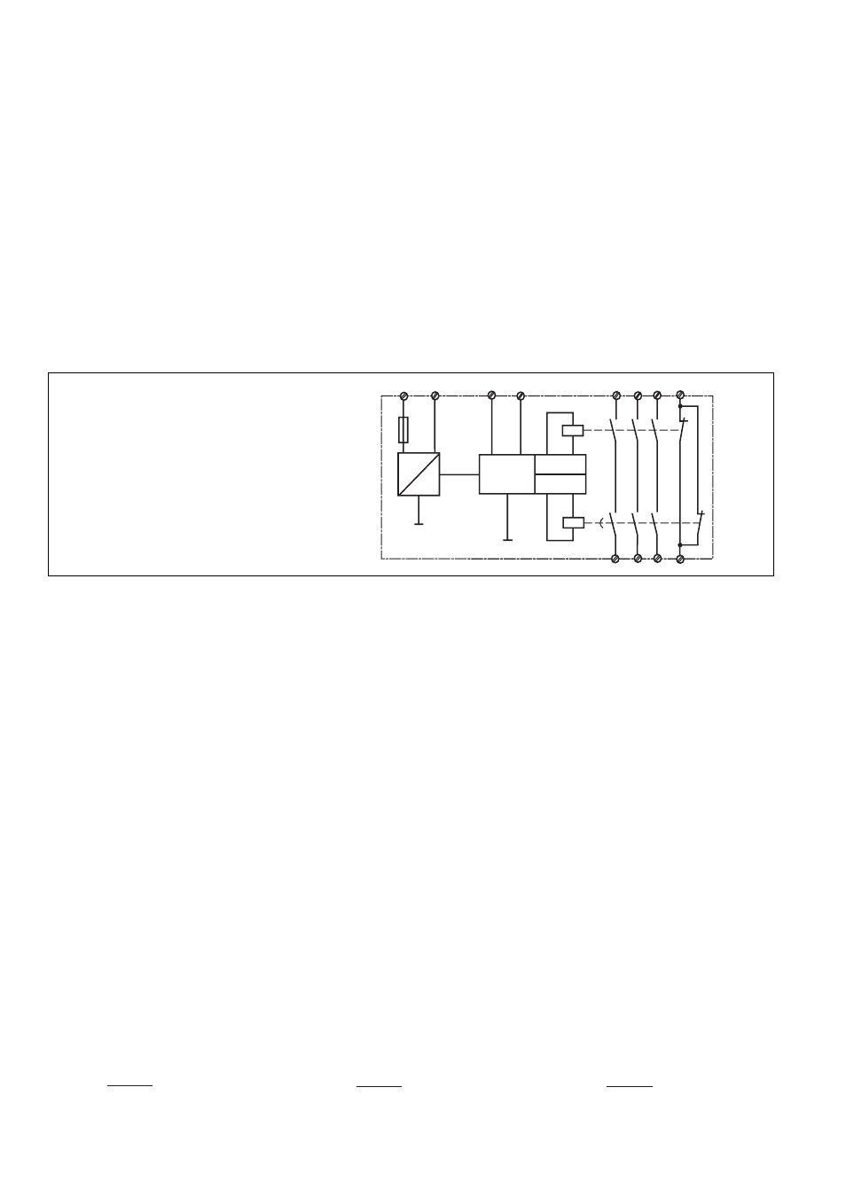
A: Einschaltlogik, zyklischer Test,
Steuerlogik/
Operating Logic, Cycle Test, Control
Logic/
Logique d'entrée, test cyclique,
logique de commande
1: Kanal 1/Channel 1/Canal 1
2: Kanal 2/Channel 2/Canal 2
Operating Modes
• Single-channel operation: Input wiring
according to VDE 0113 and EN 60204, no
redundancy in the input circuit, earth faults
are detected in the emergency stop circuit.
• Automatic reset: Unit is active, as soon as
the input circuit is closed.
• Manual reset: Unit is only active, when a
reset button has been pressed.
• Increase in the number of available
contacts by connection of external
contactors/relays.
Mode de fonctionnements :
• commande par 1 canal : conforme aux
prescriptions de la norme EN 60204, pas
de redondance dans le circuit d'entrée, la
mise à la terre du circuit d'entrée est
détectée.
• Réarmement automatique : le relais est
activé dès la fermeture du circuit d'entrée.
• Réarmement manuel : le relais n'est activé
qu'après une impulsion sur le poussoir de
réarmement.
• Augmentation du nombre de contacts ou
du pouvoir de coupure par l'utilisation de
contacteurs externes.
Installation
The safety relay must be panel mounted
(min. IP54). There is a notch on the rear of
the unit for DIN-Rail attachment.
If the unit is installed on a vertical mounting
rail (35 mm), ensure it is secured using a
fixing bracket such as end bracket.
Operation
Please note for operation:
• To prevent a welding together of the
contacts, a fuse (see technical detail)
must be connected before the output
contacts.
• Calculate the max. Cable runs I
max
in the
input circuit:
R
lmax
R
l
/ km
I
max
=
R
lmax
= Max. Total cable resistance
(see technical details)
R
l
/km = Cable resistance/km
Montage
Le relais doit être monté dans l'armoire
électrique ayant au min. un indice de
protection IP54. Sa face arrière permet un
montage rapide sur rail DIN.
Immobilisez l'appareil monté sur un rail DIN
vertical (35 mm) à l'aide d'un élément de
maintien comme par ex. un support ou une
équerre terminale.
Mise en oeuvre
Remarques préléminaires :
• protection des contacts de sortie par
des fusibles (voir les caractéristiques
techniques) normaux pour éviter leur
soudage.
• Calcular les longueurs de câblage max
I
max
dans le circuit d’entrée:
R
lmax
R
l
/ km
I
max
=
R
lmax
= résistivité de câblage totale max.
(voir les caractéristiques techniques)
R
l
/km = résistivité de câblage/km
Fig. 1: Schematisches Schaltbild/
Connection Diagram/
Schéma de principe