Pilz PNOZ X7P C 24VAC/DC 2n/o User Manual
Page 3
- 3 -
Montage
Das Sicherheitsschaltgerät muss in einen
Schaltschrank mit einer Schutzart von
mind. IP54 eingebaut werden. Zur Befesti-
gung auf einer Normschiene hat das Gerät
ein Rastelement auf der Rückseite.
Sichern Sie das Gerät bei Montage auf
einer senkrechten Tragschiene (35 mm)
durch ein Halteelement wie z. B. Endhalter
oder Endwinkel.
Inbetriebnahme
Beachten Sie bei der Inbetriebnahme:
• Vor die Ausgangskontakte eine
Sicherung (6 A flink oder 4 A träge)
schalten, um das Verschweißen der
Kontakte zu verhindern.
• Berechnung der max. Leitungslänge I
max
im Eingangskreis:
R
lmax
R
l
/ km
I
max
=
R
lmax
= max. Gesamtleitungswiderstand
(s. technische Daten)
R
l
/km = Leitungswiderstand/km
• PNOZ X7P AC:
- Ringleitung, 1 Phase (s. Fig. 3): 1 km
- Stichleitung (s. Fig. 4): max. Länge der
Stichleitung l
s
und max. Kabelkapazität
C
L
in Abhängigkeit der Versorgungs-
spannung U
B
:
U
B
[V] 42
48
110 115 120 230 240
C
L
[nF] 37,5 37,5 37,5 37,5 37,5 7,5 7,5
Werte für die max. Kabelkapazität C
L
unbedingt einhalten, sonst kann das
Gerät fehlerhaft reagieren.
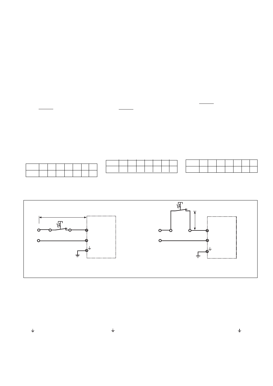
Fig. 3: Leitungslänge lr bei Ringleitung/Cable length Ir
with a ring circuit/Longueur de câblage lr en
boucle
A2
A1
UB
l
r
N
PNOZ X7P AC
A2
A1
UB
l
s
N
PNOZ X7P AC
Fig. 4: Leitungslänge ls der Stichleitung/Cable length
Is of the branch line/Longueur câblage Is en
dérivation
• Keine kleinen Ströme mit Kontakten
schalten, über die zuvor große
Ströme geführt wurden.
• Leitungsmaterial aus Kupferdraht mit
einer Temperaturbeständigkeit von
60/75 °C verwenden.
• Geräte unbedingt erden:
- PNOZ X7P 24 V AC/DC an
Anschlussklemme A2
- PNOZ X7P AC an Anschlussklemme
Nur so kann das Gerät Erdschlüsse im
Stromkreis Y1-Y2 erkennen.
• Angaben im Kapitel "Technische Daten"
unbedingt einhalten.
Installation
The safety relay must be panel mounted
(min. IP54). There is a notch on the rear of
the unit for DIN-Rail attachment. If the unit
is installed on a vertical mounting rail (35
mm), ensure it is secured using a fixing
bracket such as end bracket.
• Low currents should not be switched
across contacts across which high
currents have previously been
switched.
• Use copper wire that can withstand
60/75 °C.
• The unit must be earthed
- PNOZ X7P 24 VDC/AC at the
connection terminal A2
- PNOZ X7P AC at the terminal marked
This enables earth faults in the circuit
Y1-Y2 to be detected
• Important details in the section
“Technical Data” should be noted and
adhered to.
Montage
Le relais doit être monté dans l'armoire
électrique ayant au min. un indice de
protection IP54. Sa face arrière permet un
montage rapide sur rail DIN. Immobilisez
l'appareil monté sur un rail DIN vertical (35
mm) à l'aide d'un élément de maintien
comme par ex. un support ou une équerre
terminale.
• Ne pas commuter de faibles
intensités par des contacts ayant au
préalable commutés des intensités
plus élevées.
• Utiliser uniquement des fils de câblage
en cuivre 60/75 °C.
• Le PNOZ X7P doit être toujours relié à la
terre :
- PNOZ X7P 24 V DC/AC par la borne
A2
- PNOZ X7P AC par la borne
Ce câblage permet de détecter une mise
à la terre du circuit Y1-Y2.
• Respectez les données indiquées dans
les caractéristiques techniques.
Operation
Please note for operation:
• To prevent contact welding, a fuse
(6 A quick / 4 A slow acting) must be
connected before the output
contacts.
• Calculate the max. cable runs l
max
in the
input circuit:
R
lmax
R
l
/ km
I
max
=
R
lmax
= Max. Total cable resistance
(see technical details)
R
l
/km = cable resistance/km
• PNOZ X7P AC:
- ring circuit (Fig. 3): 1 km
- branch line (Fig. 4): max. length of the
branch line I
s
and max. capacity will
depend on the supply voltage U
B
:
U
B
[V]
42
48
110 115 120 230 240
C
L
[nF] 37,5 37,5 37,5 37,5 37,5 7,5 7,5
Values for the max. capable capacity C
L
must be adhered to, otherwise the unit
could malfunction.
Mise en oeuvre
Remarques préléminaires :
• Protection des contacts de sortie par
des fusibles 6 A rapides ou 4 A
normaux pour éviter leur soudage.
• Calcular les longueurs de câblage max
I
max
dans le circuit d’entrée:
R
lmax
R
l
/ km
I
max
=
R
lmax
= résistivité de câblage totale max.
(voir les caractéristiques techniques)
R
l
/km = résistivité de câblage/km
• PNOZ X7P AC:
- Câblage en boucle (v. Fig. 3): 1 km
- Câblage en dérivation (v. Fig. 4): long.
max. de la dérivation l
s
et capacité
max. dépend de la tension
d'alimentation U
B
:
U
B
[V]
42
48
110 115 120 230 240
C
L
[nF] 37,5 37,5 37,5 37,5 37,5 7,5 7,5
Respecter impérativement la capacité
max. C
L
du câble pour prévenir un
mauvais fonctionnement du relais.