Anwendung, Application, Utilisation – Pilz PNOZ X3.2 230VAC 24VDC 3n/o 1n/c 1so User Manual
Page 4
- 4 -
• Startkreis:
- Automatischer Start: S13-S14 brücken.
- Manueller Start mit Überwachung:
Taster an S33-S34 anschließen (S13-
S14 offen)
• Eingangskreis:
- Einkanalig: S21-S22 und S31-S32
brücken. Öffnerkontakt von Auslöse-
element an S11 und S12 anschließen.
- Zweikanalig: S11-S12 brücken.
Öffnerkontakt von Auslöseelement an
S21-S22 und S31-S32 anschließen.
•
Rückführkreis:
Externe Schütze in Reihe zu Startkreis
S13-S14 bzw. S33-S34 anschließen.
• 24 V Versorgungsspannung für Halbleiter-
ausgang: +24 V DC an Klemme Y31 und
0 V an Klemme B2 anschließen, zusätzlich
0 V der SPS mit B2 verbinden
Die Sicherheitskontakte sind aktiviert (ge-
schlossen) und der Hilfskontakt 41-42 ist ge-
öffnet. Die Statusanzeige für "CH.1", "CH.2"
leuchten. Das Gerät ist betriebsbereit. Wird
der Eingangskreis geöffnet, öffnen die
Sicherheitskontakte 13-14/23-24/33-34 und
der Hilfskontakt 41-42 schließt. Die Status-
anzeige erlischt.
Wieder aktivieren
• Eingangskreis schließen.
• Bei manuellem Start mit Überwachung
Taster zwischen S33 und S34 betätigen.
Die Statusanzeigen leuchten wieder, die
Sicherheitskontakte sind geschlossen.
Anwendung
In Fig. 2 ... Fig. 10 sind Anschlussbeispiele
für Not-Halt-Beschaltung mit automatischem
und überwachtem Start, Schutztüran-
steuerungen sowie Kontaktvervielfachung
durch externe Schütze dargestellt.
Bitte beachten Sie:
• Fig. 2 und 7: Das Gerät startet bei Span-
nungsausfall und -wiederkehr auto-
matisch. Verhindern Sie einen unerwar-
teten Wiederanlauf durch externe
Schaltungsmaßnahmen.
• Fig. 2 und 7: keine Verbindung S33-S34
• Fig. 3, 4 und 5, 6:
keine Verbindung S13-S14
• Fig. 7: Automatischer Start bei Schutztür-
steuerung: Das Gerät ist bei geöffneter
Schutztür über den Startkreis S13-S14 start-
bereit. Nach Schließen der Eingangskreise
S11-S12, S21-S22 und S31-S32 werden die
Sicherheitskontakte geschlossen.
• Reset circuit:
- Automatic reset: Bridge S13-S14
- Manual reset with monitoring: Connect
button to S33-S34 (S13-S14 open).
• Input circuit:
- Single-channel: Bridge S21-S22 and
S31-S32. Connect N/C contact from
safety switch (e.g. Emergency-Stop) to
S12 and S11.
- Two-channel: Bridge S11-S12. Connect
N/C contact from safety switch (e.g.
Emergency-Stop) to S21-S22 and S31-
S32.
• Feedback control loop:
Connect external relays/contactors in
series to reset circuit S13-S14 or S33-S34
• 24 VDC supply voltage for semi-conductor
output: Connect +24 V DC to terminals
Y31 and 0 V DC to B2, additionally
connect 0 V of the PLC to B2.
The safety contacts are activated (closed)
and the auxiliary contact (41-42) is open. The
status indicators "CH.1"and "CH.2" are
illuminated. The unit is ready for operation. If
the input circuit is opened, the safety
contacts 13-14/23-24, 33-34 open and the
auxiliary contact 41-42 closes. The status
indicator goes out.
Reactivation
• Close the input circuit.
• For manual reset with monitoring, press
the button between S33-S34.
The status indicators light up again, the
safety contacts are closed.
Application
In Fig. 2 ... Fig. 10 are connection examples
for Emergency Stop wiring with automatic
and monitored reset. Safety gate controls as
well as contact expansion via external
contactors.
• Fig. 2 and 7: the device starts auto-
matically after loss of power. You should
prevent an unintended start-up by using
external circuitry measures.
• Fig. 2 and 7: S33-S34 not connected
• Fig 3, 4 and 5, 6: S13-S14 not connected
• Fig. 7: Automatic reset with safety gate
control: with the safety gate open the unit
is ready for operation via reset circuit S13-
S14. After closing the safety input circuit
S11-S12, S21, S22 and S31-S32 the
safety contacts will close.
• Circuit de réarmement:
- réarmement automatique: pontage des
bornes S13-S14
- réarmement manuel auto-côntrolé:
câblage d'un poussoir sur S33-S34
(S13-S14 ouvert).
• Circuits d’entrée:
- Commande par 1 canal : câblage du
contact à ouverture entre S11-S12,
pontage entre S21-S22 et S31-S32
- Commande par 2 canaux: câblage des
contacts à ouverture entre S21-S22 et
S31-S32, pontage entre S11-S12
• Boucle de retour:
câbler les contacts des contacteurs
externes en série dans le circuit de
réarmement S13-S14 ou S33-S34
• Alimentation 24 V DC de la sortie statique:
relier le +24 V DC à la borne Y31 et le 0 V
à la borne B2, relier également le 0 V de
l'API à B2.
Les contacts de sécurité se ferment et le
contact d’information 41-42 s’ouvre. Les
LEDs "CH.1"et "CH.2" sont allumées.
L’appareil est prêt à fonctionner.
Si le circuit d’entrée est ouvert, les contacts
de sécurité retombent et le contact
d’information 41-42 se ferme. Les LEDs
s’éteignent.
Remise en route :
• fermer le circuit d’entrée
• en cas de surveillance du circuit de
réarmement, appuyer le poussoir de
validation S33-S34.
Les affichages d'état s'allument à nouveau.
Les contacts de sécurité sont fermées.
Utilisation
Les figures 2 à 10 représentent les différents
câblages possibles du PNOZ X3.2 à savoir :
poussoir AU avec réarmement automatique
ou auto-côntrolé, interrupteurs de position et
augmentation du nombre des contacts de
sécurité par contacteurs externes.
• Fig. 2 et 7: l’appareil se réarme
automatiquement après une coupure et
une remise sous tension. Evitez tout risque
de redémarrage par un câblage externe
approprié.
• Fig. 2 et 7: pas de câblage sur S33-S34
• Fig. 3, 4 et 5, 6:
pas de câblage sur S13-S14
• Fig. 7: Réarmement automatique en cas
de surveillance protecteur: lorsque le
protecteur est ouvert, le circuit S13-S14 se
ferme et le relais est prêt à fonctionner.
Dès la fermeture des canaux d'entrée S11-
S12, S21-S22 et S31-S32, les contacts de
sortie du relais se ferment.
S21
S22
S12
S34
S32
S33
S11
S31
S1
S3
S11 S31
S13
S12
S14
S32
S21
S22
S1
S11 S31
S33
S12
S34
S32
S21
S22
S1
S3
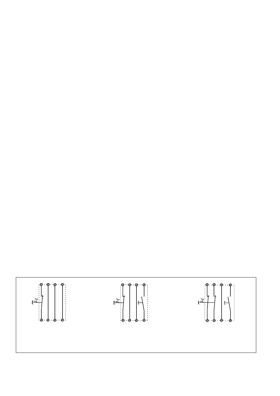
Fig. 4: Eingangskreis zweikanalig, überwach-
ter Start/Two-channel input circuit, monitored
reset/ Commande par 2 canaux, surveillance
du poussoir de validation
Fig. 3: Eingangskreis einkanalig, überwach-
ter Start/Single-channel input circuit,
monitored reset/Commande par 1 canal,
surveillance du poussoir de validation
Fig. 2: Eingangskreis einkanalig, automat.
Start/Single-channel input circuit, automatic
reset/Commande par 1 canal, validation
automatique