Pilz PNOZ 15 24VDC 3n/o 1n/o 1n/c User Manual
Page 4
- 4 -
Zweikanaliger Betrieb mit Querschlusser-
kennung:
- Automatischer Start: S12-S34 brücken.
- Manueller Start: Taster zwischen S12-
S34
Die Sicherheitskontakte sind aktiviert, der
Hilfskontakt 41-42 ist geöffnet und der
Hilfskontakt 53-54 ist geschlossen. Die
Statusanzeigen "Kanal 1" und "Kanal 2"
leuchten. Das Gerät ist betriebsbereit.
Wird der Eingangskreis geöffnet, öffnen die
Sicherheitskontakte 13-14/23-24/33-34, der
Hilfskontakt 41-42 schließt und der Hilfs-
kontakt 53-54 öffnet. Die Statusanzeige
erlischt.
Wieder aktivieren:
• Eingangskreis schließen
• Bei manuellem Start zusätzlich Taster
zwischen S12 und S34 betätigen.
Die Statusanzeigen leuchten wieder, der
Eingangskreis ist aktiviert.
Commande en 2 canaux avec détection de
courts-circuits:
- Réarmement automatique: pontage des
bornes S12-S34
- Réarmement manuel: câblage d’un
poussoir sur S12-S34
Les contacts de sécurité et le contact d'info
53-54 sont fermés. Le contact d'info (41-42)
est ouvert Les LEDs de visualisation des
canaux d'entrée sont allumées. Le relais est
activé.
Si le circuit d'entrée est ouvert, les contacts
de sécurité 13-14/23-24 /33-34 et les
contacts d'info 53-54 s'ouvrent, le contact
d'info (41-42) se ferme . Les LEDs
s'éteignent.
Remise en route:
• fermer le circuit d'entrée
• en cas de réarmement manuel, appuyer
sur le poussoir S12-S34
Les LEDs de visualisation sont allumées. Le
relais est activé .
Dual-channel operation with detection of
shorts across the contacts:
- Automatic reset: Bridge S12-S34
- Manual reset: Connect button to S12-
S34
The safety contacts are activated, the
auxiliary contact 41 - 42 is open and the
auxiliary contact 53 - 54 is closed. The
semiconductor output Y32 is connected. The
status indicators "Channel 1" and "Channel
2" are illuminated. The unit is ready for
operation. If the circuit is opened, the safety
contacts 13-14/23-24/33-34 open, the
auxiliary contact 41 - 42 closes and the
auxiliary contact 53 - 54 opens. The status
indicator goes out.
Reactivation:
• Close the input circuit.
• With manual reset, the button between
S12 - S34 must also be pressed.
The status indicators illuminate once more,
the input circuit is activated.
S11 S21
S12 S22
S11
S52
S12
S34
Y1
Y2
S1
S3
S11
S33
S12
Y1
Y2
S34
S12
S52
S21
S22
S1
S3
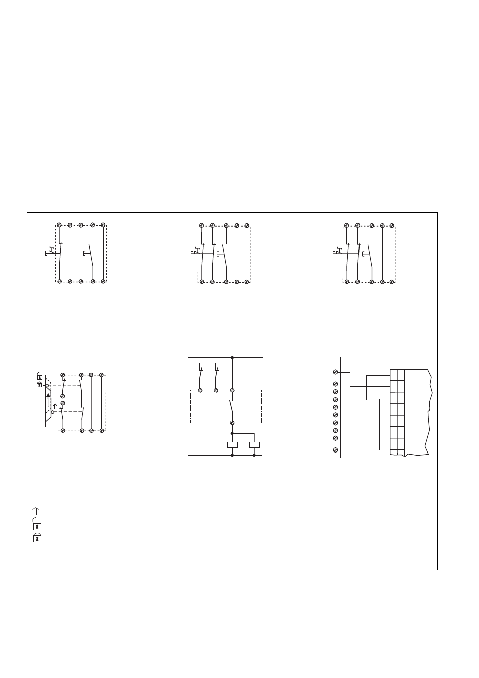
Fig. 3: Eingangskreis zweikanalig; Not-Halt-
Beschaltung; manueller Start/Two channel
input circuit: Emergency Stop wiring;
manual reset/circuit d'arrêt d'urgence
commande par 2 canaux, validation
manuelle
Fig. 2: Eingangskreis einkanalig; Not-Halt-
Beschaltung; manueller Start/Single channel
input circuit: Emergency Stop wiring;
manual reset/circuit d'arrêt d'urgence
commande par 1 canal, validation manuelle
14
K6
K7
13
Y1
Y2
K6
K7
1L1
1L2
Fig. 7: Anschlussbsp. für Halbleiteraus-
gänge/Connection of semiconductor
outputs/câblage sortie statique
Fig. 6: Anschlussbsp. für externe Schütze/
Connection of external contactors,relays/
câblage contacteurs externes
Fig. 4: Eingangskreis zweikanalig ohne
Querschlusserkennung/Two channel input
circuit; no short-circuit recognition/
Commande par 2 canaux sans détection
des c.c.
S11 S11
S12 S52
S21
S22
S33
S34
Y1
Y2
S1
S3
Fig. 5: Zweikanalige Schutztürsteuerung;
automatischer Start/Two channel safety
gate control, automatic reset/surveillance
de protecteur, réarmament automatique
S12
S11
S33
S34
S52
S1
S2
S11
S21
S22
Y1
Y2
E0.0
+ 24V
E0.1
E0.2
E0.3
A0.0
A0.1
A0.2
A0.3
0V
SPS
Y30
Y31
Y35
53
41
33
23
13
S22
PNOZ 15
S1/S2: Not-Halt- bzw. Schutztürschalter/Emergency Stop Button, Safety Gate Limit Switch/Poussoir AU, détecteurs de position
S3:
Starttaster/Reset button/Poussoir de réarmement
Tür nicht geschlossen/Gate open/porte ouverte
betätigtes Element/Switch activated/élément actionné
Tür geschlossen/Gate closed/porte fermée