Funktionsbeschreibung, Function description, Description du fonctionnement – Pilz PNOZ 15 24VDC 3n/o 1n/o 1n/c User Manual
Page 2: Montage, Installation
- 2 -
Funktionsbeschreibung
Das Schaltgerät PNOZ 15 dient dem sicher-
heitsgerichteten Unterbrechen eines Sicher-
heitsstromkreises. Nach Anlegen der Versor-
gungsspannung, Brücke zwischen Y1-Y2
und S12-S34 geht Relais K3 in Wirkstellung.
Die LED "Netz" leuchtet .
• Eingangskreis geschlossen (z. B. Not-
Halt-Taster nicht betätigt)
Relais K1 und K2 gehen über ihre
Schließer in Wirkstellung und halten sich
selbst. Die Statusanzeigen "Kanal 1" und
"Kanal 2" leuchten. Durch Öffnen der
Öffnerkontakte von K1 und K2 geht K3
nach Ablauf der Rückfallverzögerung in
Ruhestellung. Die Sicherheitskontakte
13-14/23-24/33-34 sind geschlossen, der
Hilfskontakt 41-42 ist geöffnet und der
Hilfskontakt 53-54 ist geschlossen.
• Eingangskreis wird geöffnet (z. B. Not-
Halt-Taster betätigt)
K1 und K2 fallen in die Ruhestellung
zurück. Die Sicherheitskontakte 13-14/23-
24/33-34 werden redundant geöffnet, der
Hilfskontakt 41-42 geschlossen und der
Hilfskontakt 53-54 geöffnet.
• Halbleiterausgang Y35 meldet (ist leitend),
wenn die Sicherung (Schutzschalter)
ausgelöst hat. Die LED "Störung" leuchtet.
Betriebsarten:
• Einkanaliger Betrieb:
Eingangsbeschaltung nach VDE 0113 und
EN 60204-1, keine Redundanz im
Eingangskreis; Erdschlüsse im Taster-
kreis werden erkannt.
• Zweikanaliger Betrieb: Redundanter
Eingangskreis, Erdschlüsse im Taster-
kreis und Querschlüsse zwischen den
Tasterkontakten werden erkannt.
• Automatischer Start: Gerät ist aktiv,
sobald der Eingangskreis geschlossen ist.
• Manueller Start: Gerät ist erst dann aktiv,
wenn ein Starttaster betätigt wird.
Dadurch ist ein automatischer Start des
Schaltgeräts nach Spannungsausfall und -
wiederkehr ausgeschlossen.
• Kontaktvervielfachung und -verstärkung
durch Anschluss von externen Schützen.
• u.v.a.
S21
13 23 33 41
14 24 34 42
K2
K1
K3
Y2
Y1
K3
S33
S22
S12
S52
K2
K1
S34
S11
Y31
Y30
A1
A2
A3
Y35
54
53
K4
K5
K4
K4
K5
K5
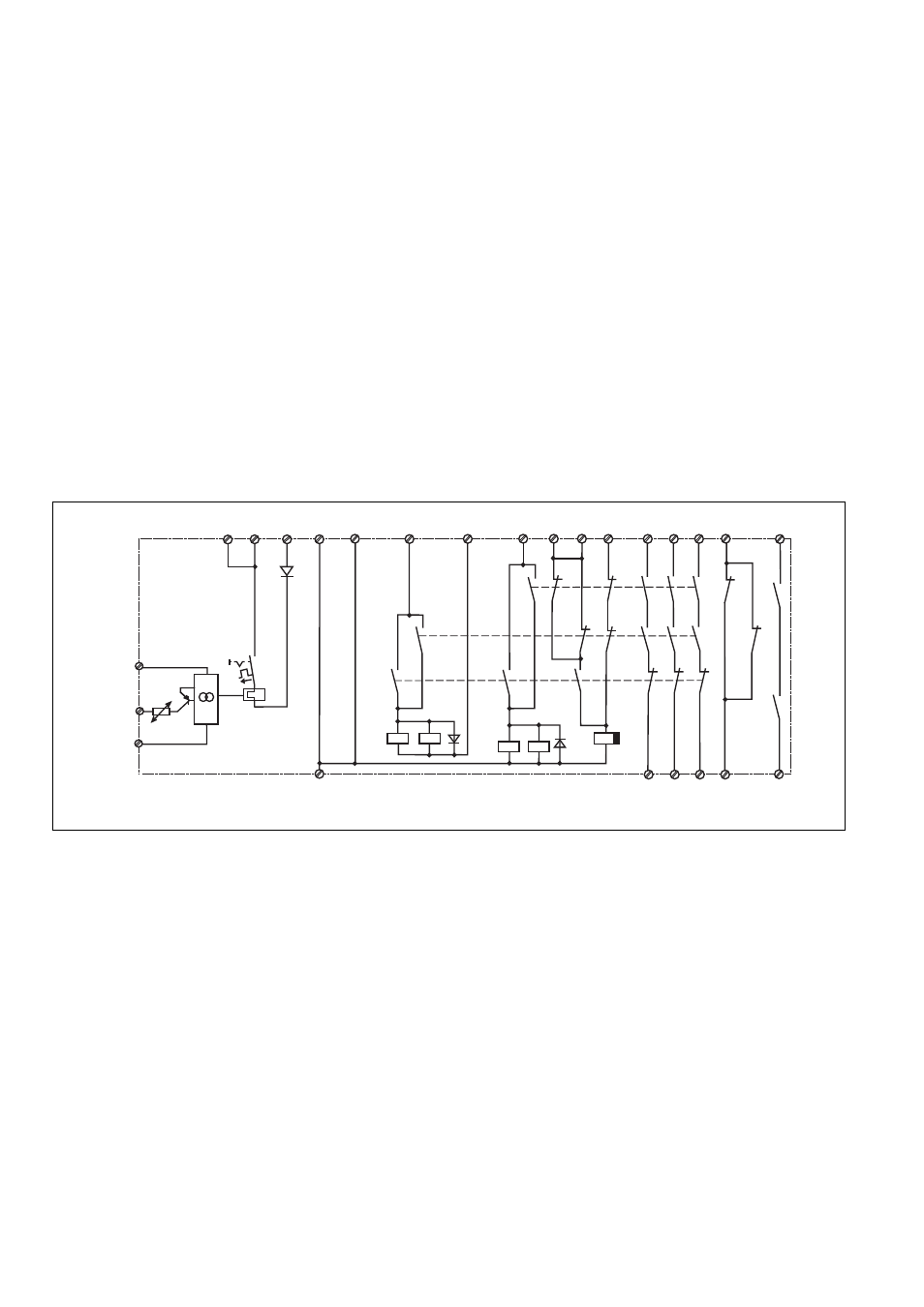
Fig. 1: Schematisches Schaltbild/Connection Diagram/schéma interne
Function Description
The PNOZ 15 provides a fail-safe
interruption of a safety related control
system. When the operating voltage is
supplied, Y1 - Y2 and S12 - S34 are
bridged, relay K3 energises. The LED
'Power' illuminates.
• Input circuit closed (e.g. Emergency Stop
Button not activated):
Relays K1 and K2 energise via their N/O
contacts and latch. The status indicators
'Channel 1' and 'Channel 2' illuminate. By
opening the N/C contacts of K1 and K2,
K3 de-energises following the delay-on
de-energisation period. The safety
contacts (13-14/23-24/33-34) are closed,
the auxiliary contact 41-42 is opened and
the auxiliary contact 53 - 54 is closed.
• Input circuit opened (e.g. Emergency Stop
Button activated):
K1 and K2 de-energise. The safety
contacts (13-14/23-24/33-34) are opened
redundantly, the auxiliary contact 41-42 is
closed and the auxiliary contact 53 - 54 is
opened.
• Semiconductor output Y35 signals (is
connected) if the fuse (cut-out) is
activated. The LED 'Fault' illuminates.
Operating Modes:
• Single-channel operation: Input wiring
according to VDE 0113 and EN 60204-1,
no redundancy in the input circuit, earth
faults are detected in the emergency stop
circuit.
• Two-channel operation: Redundancy in
the input circuit; earth faults in the
emergency stop circuit and shorts across
the emergency stop pushbutton are
detected.
• Automatic reset: Unit is active, as soon as
the input circuit is closed.
• Manual reset: Unit is only active, when a
reset button has been pressed.
Automatic reset following a loss/return of
supply voltage is thereby prevented.
• Increase in the number of available
contacts by connection of external
contactors/relays.
Description du fonctionnement
Le bloc logique PNOZ 15 assure de façon
sûre l'ouverture d'un circuit de sécurité.
Préalables: tension d'alimentation présente
et ponts entre Y1-Y2 et S12-S34, le relais
K3 colle. La LED "Netz" est allumée
• Circuit d'entrée fermé (par ex. poussoir
AU non actionné)
Les relais K1 et K2 passent en position
travail par l'intermédiaire des contacts
K3.1 et K3.2 et s'auto-maintiennent par
leur contact K1.1 et K2.1. Les LEDs de
visualisation "Kanal 1" et "Kanal 2"
s'allument. Les contacts K1.2 et K2.2
coupe l'alimentation de K3 qui retombe
après une temporisation . Les contacts de
sécurité (13-14/23-24/33-34) et le contact
d'info (53/54) se ferment, le contact
(41-42) s'ouvre.
• Circuit d'entrée s'ouvre (par ex. poussoir
AU actionné)
K1 et K2 retombent. Les contacts de
sécurité (13-14/23-24/33-34) et le
contact d'info (53-54) s'ouvrent, le
contact d'info (41-42) se ferme.
• La sortie statique Y35 est passante en
cas de déclenchement de la protection
thermique (court-circuit). La LED
"Störung" s'allume.
Mode de fonctionnements:
• commande par 1 canal: conforme aux
prescriptions de la norme EN 60204-1,
pas de redondance dans le circuit
d'entrée; la mise à la terre du circuit
d'entrée est détectée.
• commande par 2 canaux: circuit d'entrée
redondant, la mise à la terre du circuit
d'entrée et les courts-circuits entre les
contacts des AU sont détectés.
• Réarmement automatique: le relais est
activé dès la fermeture du circuit d'entrée.
• Réarmement manuel: le relais n'est activé
qu'après une impulsion sur le poussoir de
réarmement. Un réarmement automatique
du relais après une coupure d'alimentation
est ainsi impossible.
• Augmentation du nombre de contacts ou
du pouvoir de coupure par l'utilisation de
contacteurs externes
Montage
Le relais doit être monté dans l'armoire
électrique ayant au min. un indice de
protection IP54. Sa face arrière permet un
montage rapide sur rail DIN.
Montage
Das Sicherheitsschaltgerät muss in einen
Schaltschrank mit einer Schutzart von mind.
IP54 eingebaut werden. Zur Befestigung auf
einer Normschiene hat das Gerät ein
Rastelement auf der Rückseite.
Installation
The safety relay must be panel mounted
(min. IP 54). There is a notch on the rear of
the unit for DIN-Rail attachment.