Funktionsbeschreibung, Description du fonctionnement, Function description – Pilz PST 4 230 V AC 6N/O 4N/C User Manual
Page 2
- 2 -
Funktionsbeschreibung
Der Schutztürwächter PST 4 dient dem
sicherheitsgerichteten Unterbrechen eines
Sicherheitsstromkreises. Nach Anlegen der
Versorgungsspannung (LED „Netz“
leuchtet), Brücken zwischen Y1-Y2 und
S33-S34 sowie geöffneten Eingangskreisen
sind alle Relais abgefallen. Werden die
beiden Eingangskreise innerhalb der Zeit t
g
(Gleichzeitigkeitsbedingung) geschlossen,
gehen die beiden Ausgangsrelais K1 und K2
in Arbeitsstellung, die Sicherheitskontakte
schließen und die Hilfskontakte öffnen. Sind
die Eingangskreise bereits umgeschaltet,
bevor die Versorgungsspannung angelegt
wird, verhindert das PST 4 die Freigabe der
Anlage, um ein selbsttätiges Anlaufen
gemäß EN 60204 T 7.5 zu vermeiden. Wird
ein Kontakt in den Eingangskreisen betätigt,
fallen beide Relais K1 und K2 ab. Die
zwangsgeführten Sicherheitskontakte
öffnen und die Hilfskontakte schließen.
Bevor das Gerät erneut gestartet werden
kann, muss der Rückführkreis geschlossen
werden.
• Reset
Die Sicherheits- und Hilfskontakte bleiben
in Ruhestellung, wenn die Versorgungs-
spannung bei geschlossener Schutztür
angelegt wird. Öffnerkontakte in Reihe zu
den Grenztastern S1 und S2 (in Fig. 6
Taster S3) können dann das Öffnen der
Schutztür simulieren.
• Eingangskreis wieder geöffnet:
K1 und K2 fallen in Ruhestellung,
Sicherheitskontakte werden redundant
geöffnet, die Hilfskontakte geschlossen.
* Isolation zum nicht markierten Bereich und der
Relaiskontakte zueinander: Basisisolierung
(Überspannungskategorie III), sichere
Trennung (Überspannungskategorie II)
Betriebsarten:
• Zweikanaliger Betrieb: Redundanter
Eingangskreis; Erdschlüsse und Quer-
schlüsse im Tasterkreis werden erkannt.
• Automatischer Start: Gerät ist aktiv,
sobald Eingangskreis geschlossen.
• Manueller Start: Gerät ist erst dann aktiv,
wenn ein Starttaster betätigt wird.
• Kontaktvervielfachung und -verstärkung
durch Anschluss von externen Schüt-
zen; Funktionsüberwachung der
externen Schütze durch Einschleifen
von Öffnerkontakten der Schütze K3
und K4 in Reihe zu den Klemmen Y1-Y2;
über die Wahl ein- oder zweikanalige
Ansteuerung entscheidet das geforderte
Sicherheitsniveau.
Description du fonctionnement
Le relais de surveillance des protecteurs
PST 4 permet la coupure, de façon sûre,
d'un circuit de sécurité. Après la mise sous
tension (LED „Netz“allumée), si les canaux
d'entrée sont ouverts et les bornesY1-Y2 et
S33-S34 pontées, tous les relais internes
sont en position repos. Si les deux canaux
d'entrée sont fermées pendant le temps t
g
(synchronisation temporelle), les deux relais
de sortie K1 et K2 passent en position de
travail, les contacts de sécurité se ferment
et les contacts d'information s'ouvrent. Si
les canaux d'entrée sont en position de
travail avant la mise sous tension du boîtier,
le PST 4 reste au repos et empêche ainsi le
redémarrage l'installation, afin d'éviter une
mise en marche automatique selon la norme
EN 60204 T 7.5. Si les canaux d'entrée sont
ouverts, les deux relais K1 et K2 retombent.
Les contacts de sécurité s'ouvrent et les
contacts d'information se ferrment. Avant
que l'appareil ne puisse être réarmé, la
boucle de retour doit être fermée.
• Réarmement
Les contacts de sortie restent en position
repos après la mise sous tension du
boîtier si les canaux d'entrée sont
fermés. Deux contacts à ouverture
placés en série avec les capteurs S1 et
S2 (Fig. 6, poussoir S3) peuvent alors
simuler l'ouverture de la porte.
• Ouverture des canaux d'entrée :
K1 et K2 passent en position repos, les
contacts de sécurité s'ouvrent, les
contacts d'information se ferment.
* Isolation de la partie non sélectionnée par
rapport aux contacts relais : isolation basique
(catégorie de surtensions III), isolation
galvanique (catégorie de surtensions II)
Modes de fonctionnement :
• Commande en 2 canaux : rédondance
dans les canaux d'entrée : mise à la
terre et court-circuit entre les canaux
d'entrée sont détectés.
• Réarmement automatique :le PST 4 est
actif dès que les canaux d'entrée sont
fermés.
• Réarmement manuel : le PST 4 n'est actif
qu'après une impulsion sur le poussoir de
réarmement.
• Augmentation du nombre des contacts de
sécurité ou de leur pouvoir de coupure à
l'aide de contacteurs externes.
Surveillance des contacteurs externes
par câblage de contacts à ouverture de
K3 et K4 en série entre les bornes Y1-Y2;
le choix de la commande par 1 contact ou
par 2 contacts dépend du niveau de
sécurité de votre installation.
Function Description
The relay PST 4 provides a safety-oriented
interruption of a safety circuit. When the
operating voltage is supplied (LED 'power'
illuminates), Y1 - Y2 and S33 - S34 are
bridged and the input circuit is opened, all
relays drop-out. If both input circuits are
closed within the time t
g
(Simultaneity
requirement), the two output relays K1 and
K2 energise, the safety contacts close and
the signal contacts open. If the input circuits
are already closed before the operating
voltage is supplied, the PST 4 prevents
machine operation to avoid an independent
start-up according to EN 60204 Pt. 7.5. If a
contact in the input circuits is activated, both
relays K1 and K2 de-energise. The positive-
guided safety contacts open and the signal
contacts close. The unit can only be reset if
the feedback control loop is closed.
• Reset
The safety and signal contacts remain in
the starting position, if the supply voltage is
connected with the safety gate closed. N/
C contacts in series with the limit switches
S1 and S2 (in Fig. 6, switch S3) can
simulate the opening of the safety gate.
• Input circuit re-opened.
K1 and K2 go to the starting position, the
safety contacts are redundantly opened,
the signal contacts closed.
* Insulation between the non-marked area
and the relay contacts: Basic insulation
(overvoltage category III), safe separation
(overvoltage category II)
Operating Modes
• Two-channel operation: Redundancy in
the input circuit; earth faults and shorts
across contacts are detected in the
emergency stop circuit.
• Automatic reset: Unit is active, as soon as
the input circuit is closed.
• Manual reset: Unit is only active, when a
start button has been pressed.
• Increase in the number of available
contacts by connection of external
contactors/relays. Functional monitoring of
external contactors/relays by connecting
N/C contacts of relays K3 and K4 into the
existing circuit in series to the terminals Y1
- Y2; The use of 1- or 2-channel drive
depends on the risk level of your machine.
14
24
Y1
K2
K1
13
23
S11 S12
S23 S24
*
~
=
F1
G1
A2
(L-)
A1
(L+)
+
Y2
S33
S34
72
82
71
81
92
02
91
01
34
44
33
43
54
64
53
63
A
1
2
K1
K2
*
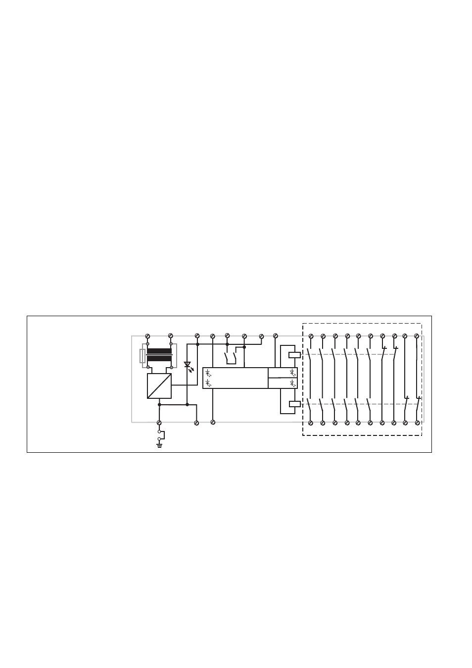
Fig. 1
Schematisches Schaltbild/
Connection Diagram/
Schéma interne
A: Einschaltlogik, zyklischer Test,
Steuerlogik/
Starting logic, cycle test,
control logic/
Logique d'entrée, test cyclique,
logique de commande
1: Kanal 1/Channel 1/canal1
2: Kanal 1/Channel 2/canal 2