Block diagram/terminal configuration, Function description, Installation – Pilz PNOZ s11 C 24VDC 8 n/o 1 n/c User Manual
Page 4
PNOZ s11
Operating Manual PNOZ s11
21693-EN-08
4
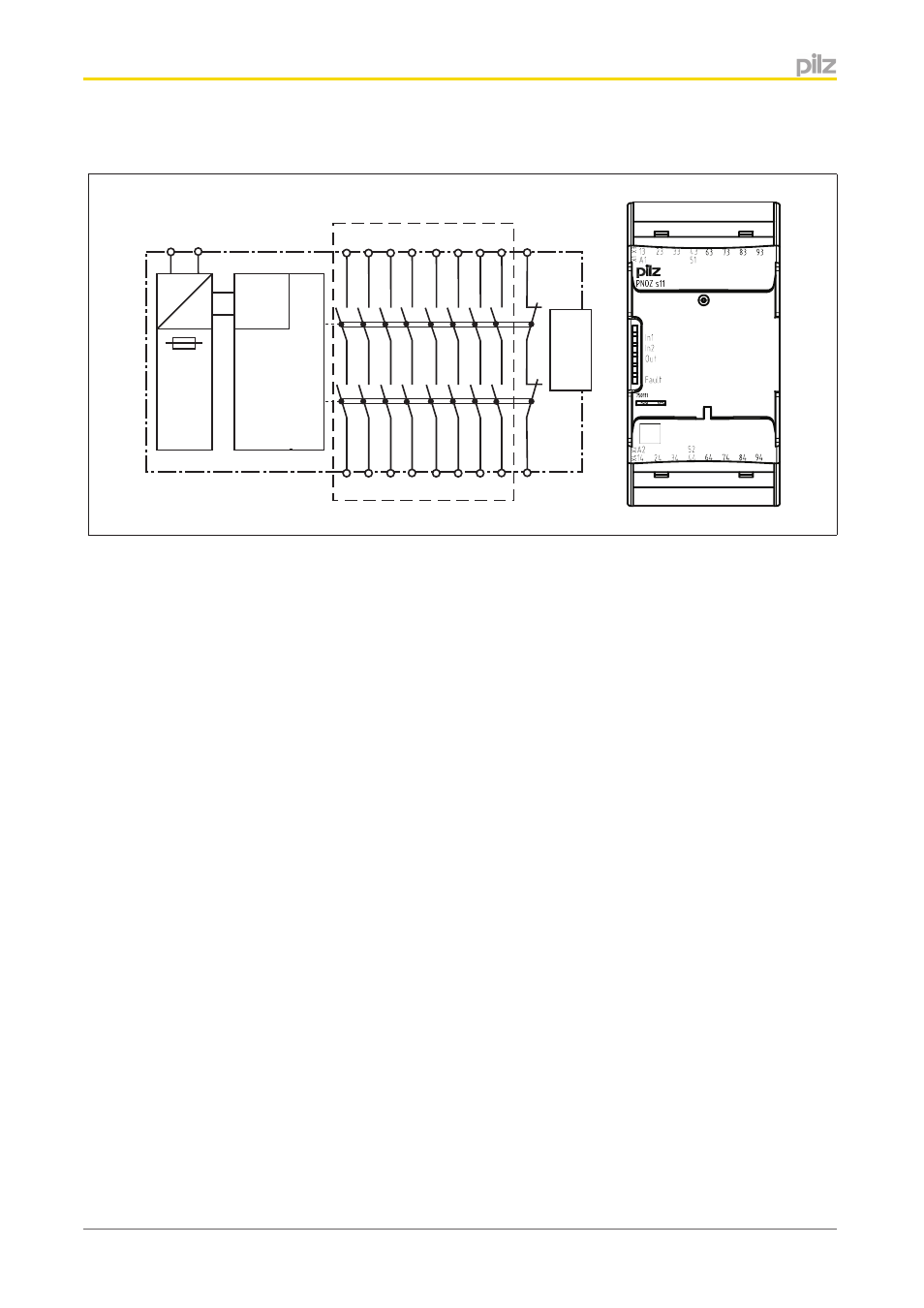
Block diagram/terminal configuration
Input
A1 A2
=
Power
=
K1
K2
13 23 33
51
24 34
52
14
43
44
*
Interface
base unit
63 73 83
74 84
64
93
94
*Safe separation in accordance with EN 60947-1, 6 kV
Function description
with PNOZsigma base unit:
}
Dual-channel operation via PNOZsigma connector
without PNOZsigma base unit:
}
Single-channel operation: one input circuit affects the output relays
Installation
Install contact expansion module without base unit:
}
Ensure that the plug terminator is inserted at the side of the unit.
Connect base unit and PNOZsigma contact expander module:
}
Remove the plug terminator at the side of the base unit and at the contact expander
module
}
Connect the base unit and the contact expansion module using the connector supplied,
before mounting the units to the DIN rail.
Control cabinet installation
}
The safety relay should be installed in a control cabinet with a protection type of at least
IP54.
}
Use the notch on the rear of the unit to attach it to a DIN rail (35 mm).
}
When installed vertically: Secure the unit by using a fixing element (e.g. retaining brack-
et or end angle).
}
Push the unit upwards or downwards before lifting it from the DIN rail.