Pilz PSEN ma1.3b-29/PSEN ma1.3-08/8mm/1 unit User Manual
Page 2
- 2 -
Seiten- und Höhenversatz
1483763979
Gesicherter Schaltabstand S
ao
in mm (typ.):
Gesicherter Ausschaltabstand S
ar
:
Max. 15 mm bei allen Höhen- und Seiten-
versätzen
Alle Angaben in mm. Die angegebenen Werte
sind gültig bei einer Temperatur von 20 °C.
Lateral and vertical offset
Assured operating distance S
ao
in mm (typ.):
Assured release distance S
ar
:
Max. 15 mm with all vertical and lateral off-
sets
All values in mm. The stated values are valid at
a temperature of 20 °C.
Décalage latéral et en hauteur
Distance de commutation de sécurité S
ao
en
mm (approximative) :
Distance de déclenchement de sécurité S
ar
:
max. 15 mm pour tous les décalages laté-
raux et en hauteur
Toutes les données sont exprimées en mm. Les
valeurs indiquées sont valables pour une tem-
pérature de 20 °C.
Verdrahtung
492354955
Beachten Sie:
Angaben im Abschnitt „Technische Daten“
unbedingt einhalten.
Berechnung der max. Leitungslänge I
max
im
Eingangskreis des Auswertegerätes:
R
lmax
= max. Gesamtleitungswiderstand
(s. techn. Daten des Auswertegeräts)
Ri = Innenwiderstand Sensor (s. techn. Da-
ten Sensor)
R
l
/ km = Leitungswiderstand/km des Ka-
bels (s. techn. Daten Kabelhersteller)
Beachten Sie bei Einsatz von Auswertegerä-
ten mit rückfallverzögerten Kontakten:
– Verzögerungszeit
≤
30 s: die rückfallverzö-
gerten Kontakte genügen den Anforderun-
gen an PDF mit Einfehlersicherheit (PDF-
S).
– Verzögerungszeit
≥
30 s: die rückfallverzö-
gerten Kontakte genügen den Anforderun-
gen an PDF mit Zuverlässigkeit durch
besonderes Design (PDF-D).
Überprüfen Sie in folgenden Fällen vor Inbe-
triebnahme die Funktion Querschlusserken-
nung:
– Bei Auswertegeräten mit Versorgungs-
spannung DC: Gesamtleitungswiderstand
≥
15 Ohm pro Kanal
– Bei Auswertegeräten mit Versorgungs-
spannung AC: Gesamtleitungswiderstand
≥
25 Ohm pro Kanal
– Wie Sie die Querschlussprüfung durchfüh-
ren müssen, entnehmen Sie der entspre-
chenden Bedienungsanleitung des
Auswertegeräts.
Wiring
Please note:
Information given in the "Technical details"
must be followed.
Calculation of the max. cable length l
max
in
the input circuit of the evaluation device:
R
lmax
= Max. overall cable resistance (see
evaluation device's techn. details)
Ri = Internal sensor resistance (see sensor's
techn. details)
R
l
/ km = Cable resistance/km (see cable
manufacturer's techn. details)
When using evaluation devices with delay-on
de-energisation contacts, please note:
– Delay time
≤
30 s: Delay-on de-energisa-
tion contacts satisfy the requirements of a
PDF with single-fault tolerance (PDF-S).
– Delay time
≥
30 s: Delay-on de-energisa-
tion contacts satisfy the requirements of a
PDF with designed reliability (PDF-D).
In the following cases, check the function
that detects shorts across contacts prior to
commissioning:
– On evaluation devices with DC supply
voltage: Overall cable resistance
≥
15
Ohms per channel
– On evaluation devices with AC supply volt-
age: Overall cable resistance
≥
25 Ohms
per channel
– For details of how to perform the test for
shorts across the contacts, please refer to
the operating manual for the relevant eval-
uation device.
Câblage
Important :
Respecter impérativement les données indi-
quées dans le paragraphe « Caractéristiques
techniques ».
Calcul de la longueur de câble max. I
max
sur
le circuit d'entrée de l'unité de contrôle :
R
lmax
= résistance max. de l'ensemble du
câblage (voir les caractéristiques techni-
ques de l'unité de contrôle)
Ri = résistance interne du capteur (voir les
caractéristiques techniques du capteur)
R
l
/ km = résistance du câble/km (voir les
caractéristiques techniques du fabricant du
câble)
Important lors de l'utilisation d'unités de con-
trôle avec contacts temporisés à la retombée
:
– Temporisation
≤
30 s : les contacts tempo-
risés à la retombée satisfont aux exigen-
ces des PDF avec sécurité de défaut
unique (PDF-S).
– Temporisation
≥
30 s : les contacts tempo-
risés à la retombée satisfont aux exigen-
ces des PDF avec une fiabilité obtenue
grâce à un design particulier (PDF-D).
Avant la mise en service, vérifiez dans les cas
suivants la fonction de détection des courts-
circuits :
– Si les unités de contrôle disposent d'une
tension d'alimentation DC : résistance de
l'ensemble du câblage
≥
15 ohm par canal
– Si les unités de contrôle disposent d'une
tension d'alimentation AC : résistance de
l'ensemble du câblage
≥
25 ohm par canal
– Consultez le manuel d'utilisation de l'unité
de contrôle pour connaître la manière
d'exécuter le contrôle des courts-circuits.
Anschlüsse
Connections
Raccordements
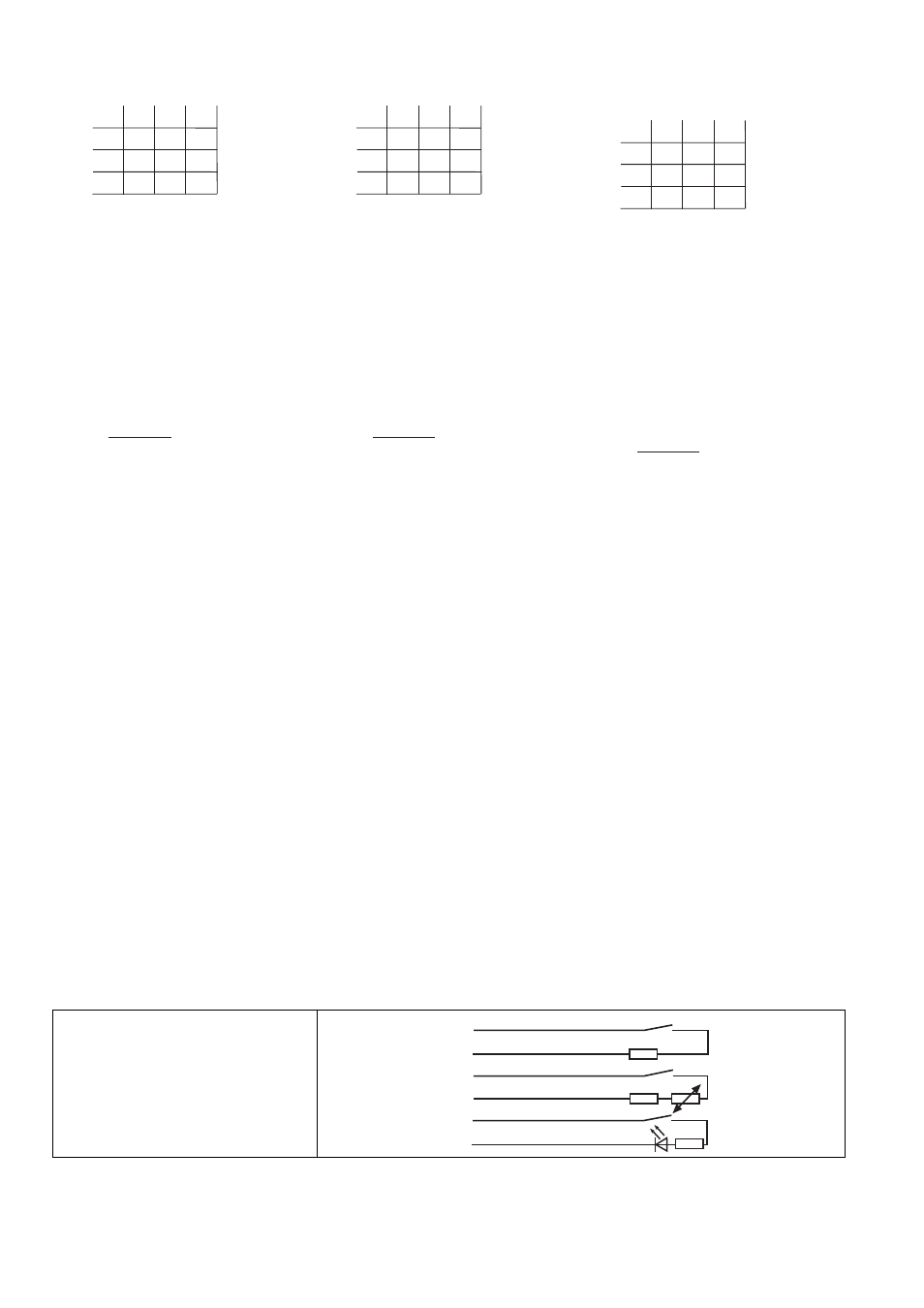
Anschlussbelegung
Pin assignment
Affectation des bornes
807841803
Der Sicherheitsschalter ist in unbetätigtem Zu-
stand dargestellt.
The safety switch is shown in an unoperated
condition.
Le capteur de sécurité est représenté en posi-
tion de repos.
Belegung des 6-adrigen Kabels/Layout of the
6-core cable/Repérage du câble à 6 conduc-
teurs
2
0
4
4
2
0
5,5
7,0
8,0
4,0
6,0
7,0
3,0
5,0
6,0
Höhenversatz/Height offset/
Décalage en hauteur
Seiten
versatz/Later
al
offset/Décalage latér
al
2
0
4
4
2
0
5,5
7,0
8,0
4,0
6,0
7,0
3,0
5,0
6,0
Höhenversatz/Height offset/
Décalage en hauteur
Seiten
versatz/Later
al
offset/Décalage latér
al
2
0
4
4
2
0
5,5
7,0
8,0
4,0
6,0
7,0
3,0
5,0
6,0
Höhenversatz/Height offset/
Décalage en hauteur
Seiten
versatz/Later
al
offset/Décalage latér
al
R
lmax
- R
i
R
l
/ km
I
max
=
R
lmax
- R
i
R
l
/ km
I
max
=
R
lmax
- R
i
R
l
/ km
I
max
=
weiß/white/blanc
braun/brown/marron
blau/blue/bleu
schwarz/black/noir
rot/red/rouge
grün/green/vert
1
2
3
4
5+
6