Pilz PSEN in1n User Manual
Page 3
- 3 -
1232909323
Bitte beachten Sie:
`
bei Verwendung eines Bedämpfungsmateri-
als von
≤
35x35x1 mm, verkleinern sich die
Schaltabstände stark.
1142438027
`
bei Verwendung von ferromagnetischen Me-
tallen gibt es einen Sperrbereich in der Nähe
der aktiven Fläche des Sensors:
– Befindet sich das dämpfende Material län-
ger als 1 s im Sperrbereich, dann schalten
die Ausgänge ab und der Sensor wird ge-
sperrt.
– Zum Entsperren des Sensors muss das
dämpfende Material von dem Sperrbe-
reich weg und über den gesicherten Aus-
schaltabstand Sar für mindestens 1 s
hinaus verschoben werden.
Please note:
`
If damping material
≤
35x35x1 mm is used,
the operating distances will be significantly
reduced.
`
If ferromagnetic metals are used, there will
be a latched zone close to the sensor's sens-
ing face:
– If the damping material is in the latched
zone for longer than 1 s, the outputs
switch off and the sensor is latched.
– To unlatch the sensor, the damping mate-
rial must be out of the latched zone and
have moved beyond the assured release
distance Sar for at least 1 s.
Tenez compte de ce qui suit :
`
en cas d'utilisation d'un matériau amortis-
sant de
≤
35x35x1 mm, les distances de com-
mutation se réduisent fortement.
`
en cas d'utilisation de métaux ferromagnéti-
ques, il existe une zone de blocage à proxi-
mité de la surface active du capteur :
– Si le matériau amortissant se trouve plus
d'une seconde dans la zone de blocage,
les sorties sont coupées et le capteur est
bloqué.
– Pour débloquer le capteur, le matériau
amortissant doit être retiré de la zone de
blocage et placé au-delà de la distance de
déclenchement de sécurité Sar pendant
au moins 1 s.
Verdrahtung
517049611
Beachten Sie:
`
Angaben im Abschnitt „Technische Daten“
unbedingt einhalten.
`
Berechnung der max. Leitungslänge I
max
im
Eingangskreis:
R
lmax
= max. Gesamtleitungswiderstand
(s. techn. Daten)
R
l
/ km = Leitungswiderstand/km
Wiring
Please note:
`
Information given in the “Technical details”
must be followed.
`
Calculation of the max. cable length l
max
in
the input circuit:
R
lmax
= max. overall cable resistance (see
Technical details)
R
l
/ km = cable resistance/km
Raccordement
Important :
`
Respectez impérativement les données indi-
quées dans la partie "Caractéristiques tech-
niques".
`
Calcul de la longueur de câble max. I
max
sur
le circuit d'entrée :
R
lmax
= résistance max. de l'ensemble du
câblage (voir les caractéristiques techni-
ques)
R
l
/ km = résistance du câblage/km
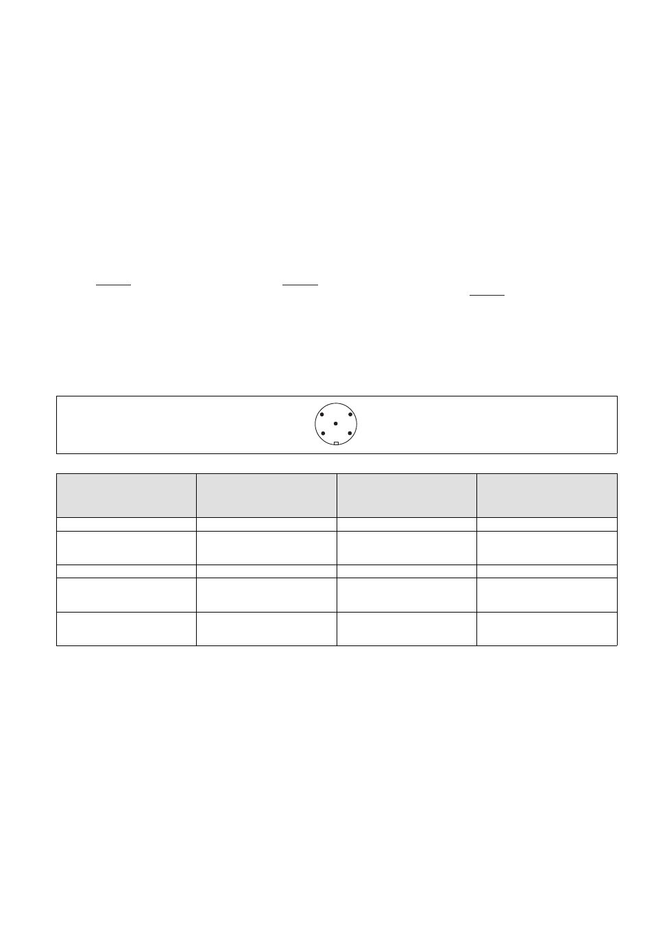
Anschlüsse
Connections
Raccordements
Stiftstecker 5-pol. M12 (male)
Connector 5-pin M12 (male)
Connecteur mâle M12 à 5 broches
Anschlussbelegung Stecker und Kabel
Pin assignment, connector and cable
Affectation des bornes - connecteur et câble
Anschlussbezeichnung im
Blockschaltbild/
Terminal designation/
Désignation des bornes
Funktion/
Function/
Foncion
PIN/
Broche
Adernfarbe (Pilz Kabel)/
Cable colour (Cable Pilz)/
Couleur du fil (fil de Pilz)
A1
+24 UB
1
braun/brown/marron
12
Ausgang Kanal 1/
Output, channel 1/
Canal de sortie 1
2
weiß/white/blanc
A2
0 V UB
3
blau/blue/bleu
22
Ausgang Kanal 2/
Output, channel 2/
Canal de sortie 2
4
schwarz/black/noir
-
nicht anschließen/
do not connect/
pas raccordé
5
grau/grey/gris
R
lmax
R
l
/ km
I
max
=
R
lmax
R
l
/ km
I
max
=
R
lmax
R
l
/ km
I
max
=
1
2
3
5
4