5 scale selection, 6 weight and balance, 5 scale selection 1.6 weight and balance – Rice Lake TradeRoute HL Series - Installation and Service Manual (Legal-for-Trade) User Manual
Page 8
4
Trade
Route Installation Manual
1.5
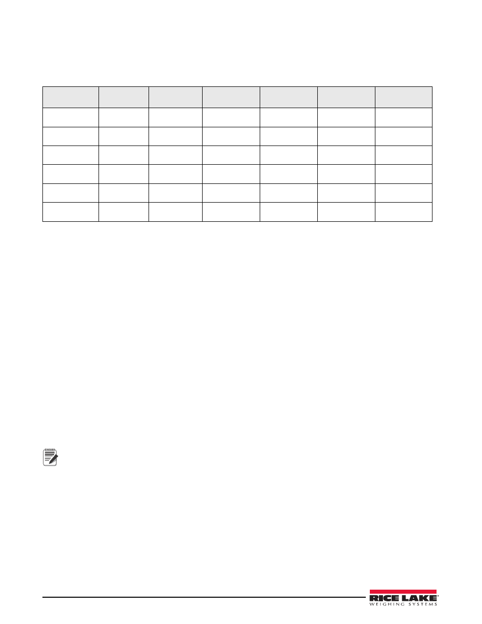
Scale Selection
The capacity of the scale selected must be able to carry the empty weight of the container/delivery body (tare
weight) plus the maximum product that can be carried by the container (maximum net weight). Use the following
chart to select the proper scale capacity.
Table 1-1. Number of Assemblies Required by Capacity
Capacity
Required
OB5-SGL5
OB10-DBL5
OB10-SGL10
OB20-DBL10
OB15-SGL15
OB30-DBL15
15,000 lb
(7000 kg)
1
1
20,000 lb
(9,000 kg)
2
30.000 lb
(13,500 kg)
1
1
40,000 lb
(18,000 kg)
2
45,000 lb
(20,000 kg)
1
1
60,000 lb
(27,000 kg)
2
1.6
Weight and Balance
The objective of the weight and balance calculation is to determine the truck’s resulting axle weights when the
system is installed. It is important that the allowable axle weight limits of the truck and allowable road limits are
not exceeded.
A worksheet outlining the calculation is shown on the following page.
1. Measure the wheelbase of the truck. This is the distance from the front axle to the center of the rear axle
group.
2. Obtain the initial axle weights of the truck without the container (delivery body).
3. Allow a minimum clearance of 2
"
from any part of the scale (scale frame, tanks) to any fixed obstruction
on the truck (cab, exhaust stacks). This is required for proper scale operation.
4. Estimate the center of gravity of the container or delivery body. The center of gravity can usually be
estimated as the center of the container.
5. Select a starting position for the body or container on the truck frame. The container center of gravity must
be ahead of the rear axle group.
6. Assuming the starting position as previously described, determine the forward distance (FD) from the
center of the rear axle group ahead to the body’s center of gravity. This dimension can be calculated or
measured with a tape measure.
7. Determine the total weight of components being installed on the truck.
8. Determine final axle weights using the equations below the worksheet.
Note
If one of the axle weights is greater than the allowable limit for the truck or roads, shift the body forward (to
lower the rear axle weight) or backward (to lower the front axle weight), keeping in mind points 3, 5 and 6
above.
9. Extend the truck frame if required. If the weigh module hangs past the end of the truck frame, the truck
frame must be extended. The truck frame must be at least even with the end of the weigh module. It is
recommended that the truck frame extend a minimum of 1
"
past the weigh module.
10. It is preferred that the rear bumper be mounted directly to the truck frame.