3 balancing procedure and corner correction – Rice Lake TradeRoute HL Series - Installation and Service Manual (Legal-for-Trade) User Manual
Page 31
920i® Electronic Weigh Center
27
3.3
Balancing Procedure and Corner Correction
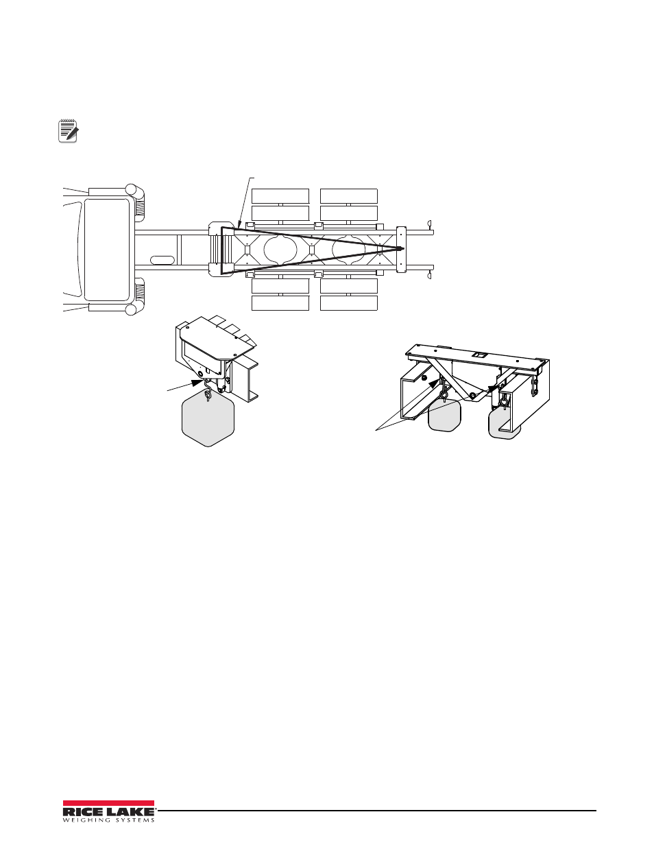
When loading test weights on the scale (for balancing or calibration), it is important to position the weights
correctly. Imagine lines connecting the load cell positions (see Figure 3-4). Keep the weights inside the area
defined by the lines connecting the load cell positions.
Loading Area
Access holes for
hanging test weights
(One hole per side)
Access holes for
hanging test weights
Double Assembly
Single Assembly
Note
Temporary racks may be required on the container to place the weights on during testing. All modules have
provisions for hanging test weights below the truck frame.
Figure 3-4. Loading Area
Before the scale can be calibrated, all load cells must be balanced and responding to loading equally by adjusting
the balance trimmers. The balance trimmers are located on the junction box (see Figure 3-5). Use the following
procedure to balance the load cells.
1. All assembled scales are delivered with the junction box corner-trimmed to verify load cell operation only.
To calibrate the scale, the output from each load cell must be matched by adjusting the signals with
potentiometers at the junction box, a process known as trimming.
a. Remove the junction box cover and identify the correct load cell terminal corresponding to each corner
(labeled CELL 1, CELL 2, and so on). See Section 2.12 for scale deck corner numbering.
b.The indicator must be connected and calibrated approximately, but it need not indicate the exact weight
value. A test weight will be required. The recommended test weight for all
Trade
Route
models is 25% of
scale capacity.
2. Ensure the load cells are all loose when in the transport mode. The lockdown bolts may have to be adjusted
if the load cell is binding. Raise and lower the scale several times to ensure the scale is hanging freely.
3. Raise the scale. “Dead load” the test rack by following the calibration procedure in Section 3.1. Load
weights on the rack to the full capacity of the scale and then unload all the weights. This process
“exercises” the load cells.
4. Press the zero key to obtain a good center of zero. Load one load cell by placing the balancing weights on
that corner of the tank (inside the triangle noted above). Keep the weights as close to the load cell as
possible directly above the load cell being calibrated. Record the weight on the 920i. The weight reading
should be close to the actual weight applied at this point in the procedure; however, it does not need to be
exact.