0 scale installation, 1 truck preparation, 1 fenders – Rice Lake TradeRoute HL Series - Installation and Service Manual (Legal-for-Trade) User Manual
Page 10: 2 scale positioning, 1 three-cell system
6
Trade
Route Installation Manual
2.0
Scale Installation
2.1
Truck Preparation
Before you mount the
Trade
Route
system onto your truck, make sure there are no protrusions or mechanical parts
on the truck that may interfere with the scale operation. Remove any parts that protrude above the c-channel of the
truck frame.
2.1.1
Fenders
Fenders are required over the rear wheels of the truck. This prevents mud/dirt accumulation on the scale that can
cause erroneous weight indications. The truck fenders must be mounted on the truck frame, NOT on the container
body. Allow for a minimum 3
"
clearance between the fenders and any part of the scale.
2.2
Scale Positioning
The scale must be correctly positioned in relation to the container’s center of gravity to ensure proper distribution
of weight to the load cells. The following diagrams outline the proper scale positioning for three point and four
point scales. For three point systems, Rice Lake Weighing Systems recommends positioning the single cell in the
rear to avoid the truck’s driveshaft. There is no front or back to the modules; they can be attached in either
direction. Some factors to consider when positioning the modules are:
• Accessibility for service
• Space for attachment of test weights to the lift plates of the scale system
• Avoidance of bolt heads on the truck frame
• Avoidance of other protruding components on the truck frame
• Ease of hydraulic plumbing and wire routing
• Location of reed switch alarm, installed at front of truck
It is important to position the scale far enough away from axles and tires so weight hangers and test weights can be
attached to the lift plates for balancing, calibration, and approval. The test weights, when attached to the scale,
must clear all obstructions at all operative angles (6 degrees in all directions). See the Figure 2-1 and Figure 2-2
for details.
2.2.1
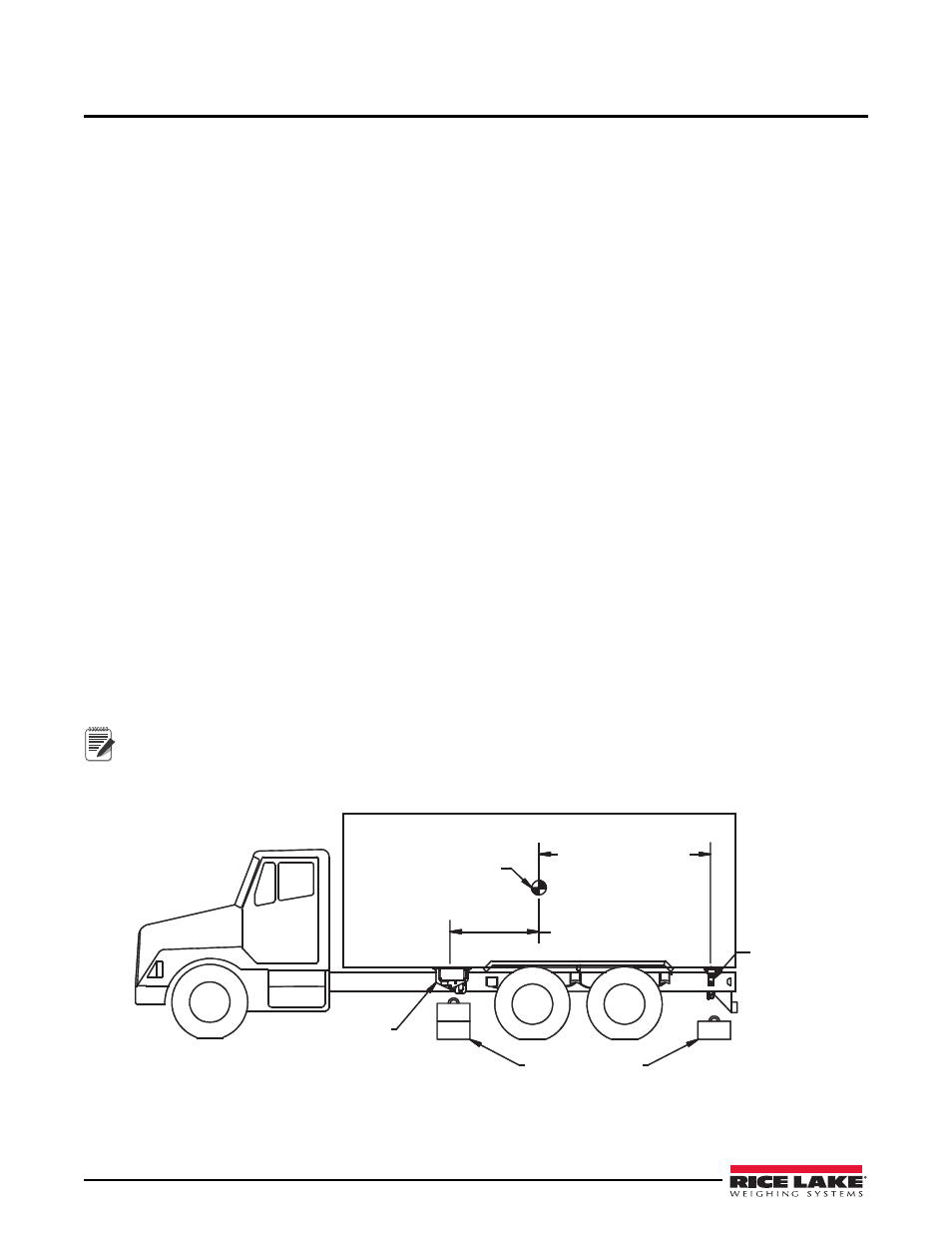
Three-Cell System
(One single and one double cell assembly)
Center of Gravity
Distance to
Single Cell = 2X
Distance to
Double Cells = X
Single
Cell
Assembly
Allow Room for
Test Weights
Double Cell
Assembly
Note
The distance from the container’s center of gravity to the single load cell assembly must be double the
distance from the container’s center of gravity to the double load cell assembly.
Figure 2-1. Double / Single Scale Positioning