5 board removal, 6 replacement parts, 7 instrumentation setup – Rice Lake IQ 700 Configurable Weight Indicator User Manual
Page 9: Ep–1.15, Caution, Eprom set 1 version 15
Installation and Wiring
5
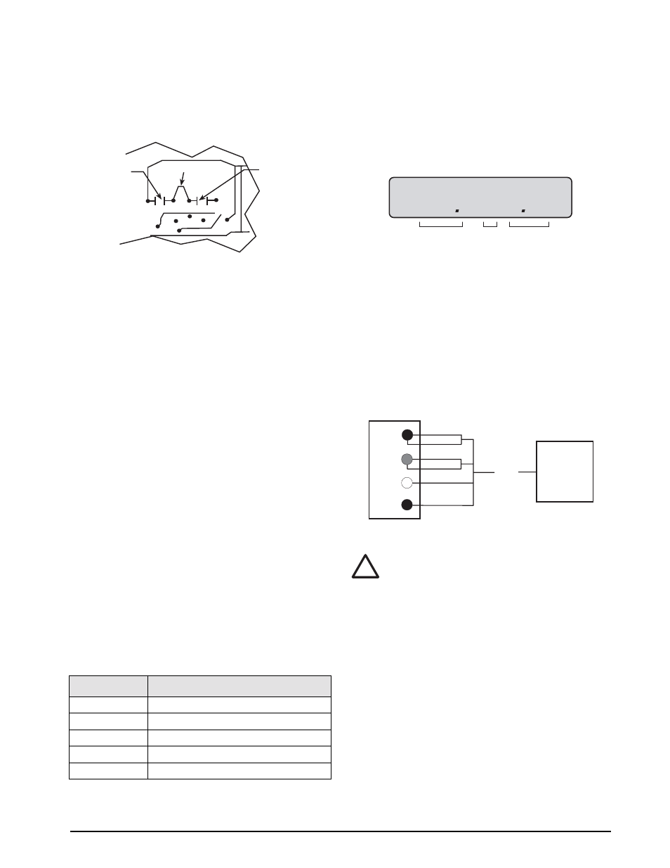
6. Cut circuit traces between E7/E8 and E9/E10 as
indicated with a sharp instrument like a razor
blade or an X-acto
®
Figure 2-2. Circuit Trace Setup
7. Add jumper, E8 to E9 using a properly insulated
wire with a minimum size of #22 AWG.
8. Replace the protective insulator panel.
9. Change the power cord.
10. Reassemble the unit, test, and label unit for
230VAC.
2.5
Board Removal
If you must remove the IQ 700 CPU board, use the
following procedure:
1. Disconnect power to the indicator. Loosen cord
grips and remove enclosure as described in
Section 2.2.
2. Unplug all connections to the CPU board.
3. Remove the four corner screws from the
standoffs.
4. Remove the four screws from the corners of the
CPU board.
5. Remove the CPU board from the enclosure.
To replace the CPU board, reverse the procedure. Be
sure to reinstall cable ties to secure all cables inside the
indicator enclosure. Replace the enclosure and torque
screws.
2.6
Replacement Parts
Table 2-1 lists the replacement parts for the IQ 700.
2.7
Instrumentation Setup
The IQ 700 operates with the EPROM program
KDA1921-1(27C512). To verify the program installed
in the indicator, turn on the indicator and observe the
displayed value at the EP prompt (see Figure 2-3). The
EP prompt displays the family, set, and version level of
the installed EPROM.
Figure 2-3. EPROM Display
To ensure that the IQ 700 is in proper operating
condition, the indicator can be tested with a load cell
simulator. The input signal should be as close as
possible to the normal system millivolt value.
Figure
2-4 shows the simulator-to-indicator wiring
connection in a six-wire configuration. See Section 2.8
on page 6 for more information.
NOTE:
Six-wire configuration requires that the +SEN
lead be shorted to +EXC and the –SEN lead be shorted
to –EXC at the simulator only.
Figure 2-4. Wiring Connection to Simulator
Exceeding rated load cell load or
shorting excitation wires may
damage power supply.
19571
AC CPU RFI assembly
19573
LED display board
19574
21-keyboard assembly
19404
Overlay
19600
LCD display board
Table 2-1. IQ 700 Replacement Parts
E7
E8 E9
E10
Jumper E8 to E9
Cut between
E7 and E8
Cut between
E9 and E10
Circuit Side of CPU Board
Converting from 115V AC to 230V AC
EP–1.15
EPROM Set 1 Version 15
LOAD CELL
SIMULATOR
TO J1
CONNECTOR
IQ700 HB
+SIG
–SIG
+EXC
–EXC
–SEN
+SEN
–EXC
+EXC
+SIG
–SIG
!
Caution