0 configuration, 1 digital configuration, 1 parameter overview – Rice Lake IQ 700 Configurable Weight Indicator User Manual
Page 16: 2 configuration procedure, 3 digital configuration parameters, Modes. 3. close switch sw1-2, marked
12
IQ 700 Installation Manual
3.0
Configuration
Prior to calibration, the IQ 700 must be digitally
configured, or assigned a set of operating parameters.
The three parameters listed in Section 3.1 are directly
related to calibration and must be set before proceeding
to calibration mode.
3.1
Digital Configuration
3.1.1
Parameter Overview
Table 3-1 on page 13 lists configuration parameters and
describes their values. The following paragraphs give
the procedure for configuring the IQ 700.
3.1.2
Configuration Procedure
1. Unscrew the two screws on the face plate
bracket (Figure 3-1). The bracket drops down,
exposing four program switches on the left.
Figure 3-1. Accessing the Program Switches
2. Temporarily remove the unit’s flexible black
display panel by gently pushing down and lifting
the panel up and out at its center to expose the
configuration and calibration instructions printed
on the surface below. The switch function table
defines the appropriate front panel switch
settings for the
CONF
and
CAL
modes.
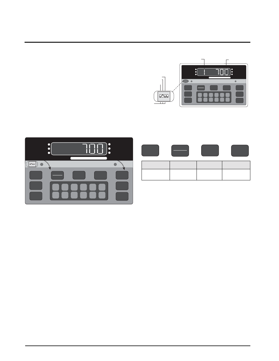
3. Close switch SW1-2, marked
CONF
(2), by
moving to the up position (see Figure 3-2). A
prompt appears with a parameter number and
data value.
The parameter identifier is a number, 1–14, that
correlates to the
CONFIG
chart on the upper left of the
switch map panel. Selected data represents the value
being entered into the unit configuration data. For
example, 1 100 sets the indicator to 10,000 graduations
(see Table 3-2 on page 15).
When configuration is complete, set SW1-2 down to
return the unit to normal operating mode.
Figure 3-2. Closing Switch 2
Figure 3-3 defines the functional operation of each key
on the front panel of the indicator when the unit is in the
the setup mode.
Figure 3-3. Front Panel Key Functions
NOTE: The TARE RECALL key functions as a previous
screen key in CONFIG mode.
3.1.3
Digital Configuration Parameters
Table 3-2 on page 15 lists the configuration display
prompts (Prompt 1), and their value selections for
displayed graduations. Prior to calibration, the IQ 700
must be digitally configured, or given its set of
operating parameters. The first three parameter
selections are directly related to calibration and must be
set up before proceeding to the calibration mode. These
parameters include;
•
number of graduation
•
resolution
•
decimal point location in the weight data, all of
which define the scale capacity.
Table 3-3 lists Prompts 2 and 3, Table 3-4 lists Prompts
4, and Table 3-4 has Prompts 5, 6, and 7. Prompts 8, 9,
and 10 are shown in Table 3-5 and Prompts 11 through
14 are listed in Table 3-6 on page 17.
1
6
2
7
3
8
4
9
5
0
CE
ENT
TARE
RECALL
ZERO
NET
GROSS
TARE
lb/kg
CONV
1 SET
POINT
2 SET
POINT
CAPACITY
5000 lb. X 0.5
ZERO
NET
GROSS
lb
kg
MOTION
M O D E L
700
3 4
2
1
OPEN
Zero
Net/Gross
Tare
Units
Parameter
Select
Parameter Data
Select
Subparameter
Select
Subparameter
Data Select
DEAD LOAD (3)
CONF (2)
CAL (1)
3 4
2
1
OPEN
NORM
1
6
2
7
3
8
4
9
5
0
CE
ENT
TARE
RECALL
ZERO
NET
GROSS
TARE
lb/kg
CONV
1 SET
POINT
2 SET
POINT
CAPACITY
5000 lb. X 0.5
ZERO
NET
GROSS
lb
kg
MOTION
M O D E L
700
Parameter Identifier
Selected Data
ZERO
NET
GROSS
TARE
lb/kg
CONV