0 calibration, 1 zero calibration, 2 single slope span calibration – Rice Lake IQ 700 Configurable Weight Indicator User Manual
Page 50: 3 4 2 1 open, As sho wn in figure 5-1, Key. the display should read, Then return to a zero reading, The display will read, Zero, Figure 5-3. sw1 with all switches open
46
IQ 700 Installation Manual
5.0
Calibration
The IQ 700 indicator can be calibrated using single slope span calibration or five-point linearization. Zero must be
calibrated (see Section 5.1) before either span or linearization calibration can be performed.
Indicator option 2 (Section 4.2 on page 22) provides settings for zero, span, and trim adjustments. The settings are
all digital therefore no potentiometers are required. During the trim adjustments for zero/span, the analog output is
forced to the zero/span previously selected in option mode parameters 2.5 and 2.6. While reading the analog output,
the trim is increased or decreased from 0 to ± 175 until the reading corresponds with the values entered in
parameters 2.5 and 2.6.
5.1
Zero Calibration
Zero calibration is accomplished by the following steps:
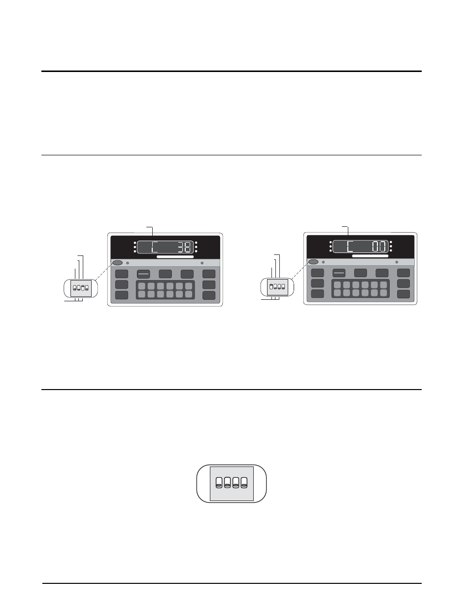
1. Clear the scale (no load).
2. Close SW1-3 (dead load). The leftmost display digit should be flashing
C
as shown in Figure 5-1.
Figure 5-1. Close Switch 3
Figure 5-2. Close Switch 3 and Open Switch 1
3. Adjust dead load potentiometer to obtain a reading at or near zero (see Figure 5-2).
4. Open SW1-3 and close SW1-1 to put the indicator in the digital calibration mode. The display may change
from a zero reading, which is acceptable.
5. Press the
ZERO
key. The display should read
---CAL
, then return to a zero reading.
5.2
Single Slope Span Calibration
1. Place a test weight on the scale and wait for the motion LED to go out.
2. Enter weight value using keyboard. When correct, press
ENT
. The display will read
---CAL
briefly, then
return to the correct reading.
3. Recheck by clearing scale.
4. Open all switches to place the unit in normal weighing mode (Figure 5-3).
Figure 5-3. SW1 with All Switches Open
5. Close center bar and tighten center bar screws. Seal the unit if used in a legal-for-trade application.
DEAD LOAD (3)
CONF (2)
CAL (1)
3 4
2
1
OPEN
NORM
1
6
2
7
3
8
4
9
5
0
CE
ENT
TARE
RECALL
ZERO
NET
GROSS
TARE
lb/kg
CONV
1 SET
POINT
2 SET
POINT
CAPACITY
5000 lb. X 0.5
ZERO
NET
GROSS
lb
kg
MOTION
M O D E L
700
FLASHING
DEAD LOAD (3)
CONF (2)
CAL (1)
3 4
2
1
OPEN
NORM
1
6
2
7
3
8
4
9
5
0
CE
ENT
TARE
RECALL
ZERO
NET
GROSS
TARE
lb/kg
CONV
1 SET
POINT
2 SET
POINT
CAPACITY
5000 lb. X 0.5
ZERO
NET
GROSS
lb
kg
MOTION
M O D E L
700
FLASHING
3 4
2
1
OPEN