2 serial port #2 wiring: cpu kgr8924–1, 11 digital i/o wiring – Rice Lake IQ 700 Configurable Weight Indicator User Manual
Page 14
10
IQ 700 Installation Manual
2.10.2
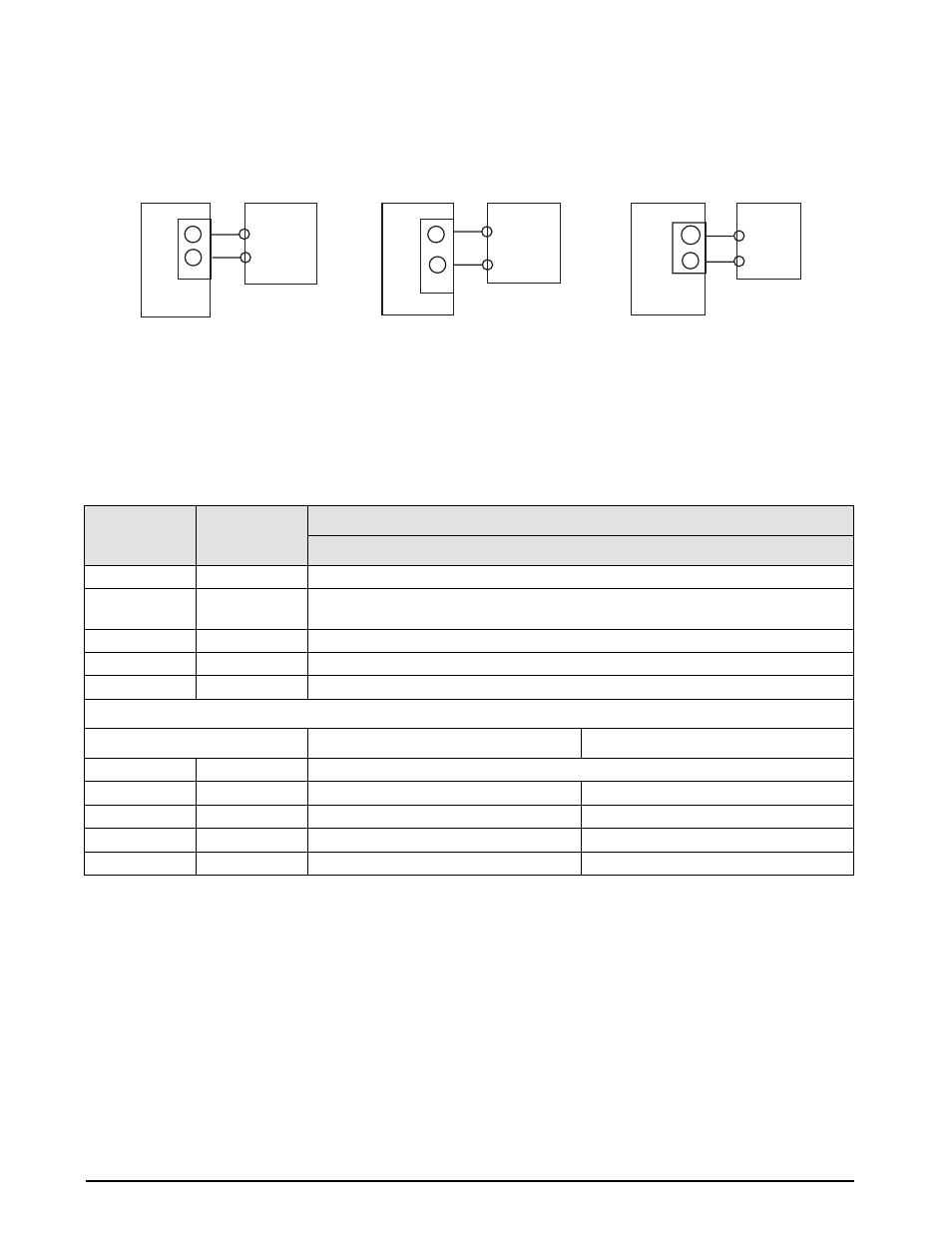
Serial Port #2 Wiring: CPU KGR8924–1
Serial port #2 is a simplex port using RS232, or 20 mA active/passive (passive 20 mA requires U15 installed)
communication.
Figure 2-13. Port #2 Switch Settings
2.11 Digital I/O Wiring
The standard unit has four outputs for setpoint and zero band control and four discrete inputs that allow the zero,
net/gross, and print function to be operated remotely by contact closure of these inputs to digital ground. Wire any
active digital input and outputs to connector TB3 on the CPU board. Table 2-3 shows the digital I/O assignments for
the TB3 connector and their description.
Inputs 7 through 10 allow the zero, net/gross, tare, and print functions to be operated remotely by contact closure of
these inputs to digital ground.
TB2
TX2
COM
PORT 2
1
5
Rx
SIG COM
RS232
TB4
TX+
active
TX-
PORT 2
1
Rx+
passive
20 mA active
TB5
TX+
TX-
PORT 2
3
active
Rx+
20 mA passive
2
Rx -
4
Rx-
TB3 Pin
Signal
Description
Outputs
1
+5 VDC
2
DIG OUT 4
Dribble control assigned to setpoint 2 (defined in parameter 11), or a zero band output
when parameter 12 is selected for 1-50.
3
DIG OUT 3
Setpoint 2 output (defined in parameter 11).
4
DIG OUT 2
Dribble control assigned to setpoint 1 (defined in parameter 11).
5
DIG OUT 1
Setpoint 1 output (defined in parameter 11).
Inputs
Normal Mode
Batch Mode
6
GND
7
DIG IN 1
Net/gross
Abort
8
DIG IN 2
Zero
Zero
9
DIG IN 3
Tare
Start Batch
10
DIG IN 4
Table 2-3. TB3 Pin Assignments (Digital I/O)