Iqube, Table 2-2. load cell connector pin assignments, Installation manual – Rice Lake Digital/Diagnostic - iQube User Manual
Page 7: Setup, J4 dac, J2 core module j3
4
iQUBE
Installation Manual
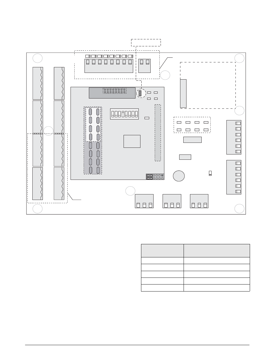
Figure 2-2.
iQUBE Connector Board (8-channel with Digital I/O) with Core Module and DAC Card
Load Cell Wiring
To attach load cell cables to the connector board, route
the cables through the cord grips on the load cell
connector end of the
iQUBE
enclosure. Note the load
cell numbering assigned to the connectors (see
Figure 2-2).
Strip 1/4-inch of insulation from the ends of the load
cell wires. Use the cable clamp tool included in the
parts kit to open the connector springs and install
wires into the connectors. Wire load cell cables as
shown in Table 2-2.
When connections are complete, use cable ties and
mounts to secure the load cell cables to the inside of
the enclosure.
+SIG
–SIG
+EXC
–EXC
SHLD
1
J12
LOAD CELL 1
J13
LOAD CELL 2
+SIG
–SIG
+EXC
–EXC
SHLD
1
J14
LOAD CELL
3
+SIG
–SIG
+EXC
–EXC
SHLD
1
J15
LOAD CELL 4
+SIG
–SIG
+EXC
–EXC
SHLD
1
J16
LOAD CELL 5
+SIG
–SIG
+EXC
–EXC
SHLD
1
J17
LOAD CELL 6
+SIG
–SIG
+EXC
–EXC
SHLD
1
J18
LOAD CELL 7
+SIG
–SIG
+EXC
–EXC
SHLD
1
J19
LOAD CELL 8
+SIG
–SIG
+EXC
–EXC
SHLD
1
J21
1
IO 8
IO 7
IO 6
IO 5
IO 4
IO
3
IO 2
IO 1
J8
ANALOG 2
+
S
IG
+
S
IG
1
1
–
S
IG
–
S
IG
S
HLD
S
H
L
D
J9
ANALOG 1
+SIG
1
–SIG
SHLD
J10
BOARD POWER
+PWR
1
GND SHLD
J11
SECONDARY
POWER
1
J4
GND
S
HLD
Z
B
Y
A
J7
GND
S
HLD
Z/TXD
A/RXD
+PWR
GND
J20
1
1
1
F1
OFF
ON
SW1
SETUP
1
J3
LED EXTENSION
J6
1
EXPAN
S
ION MODULE
GREEN =
POWER ON
DIGITAL I/O
8-CHANNEL
MODELS ONLY
DIGITAL I/O
MODEL ONLY
INPUT/OUTPUT LEDs:
OUTPUT: GREEN = RELAY ON
INPUT:
GREEN = SWITCH CLOSED
+PWR
GND SHLD
1
2
3
4
5
6
7
8
ON
J4
DAC
DIP SWITCH / S1
1
J2
CORE MODULE
J3
D1
C5
C6
C7
C8
C1
C2
C3
C4
CELL STATUS LEDs
FIBER-OPTIC OR
ETHERNET
OPTION
Y
B
Version
Label
PIN 1
D8
D6
D7
D5
C72
C73
C44
C47
C74
C75
C50
C53
C76
C77
C56
C59
C78
C79
C62
C65
4-Channel
8-Channel
JP1
JP1 is located on the back
side of the core module
Serial LEDs
Load Cell Connector
Pins (J12–J19)
Function
1
+SIG
2
–SIG
3
+EXC
4
–EXC
5
SHIELD
Table 2-2. Load Cell Connector Pin Assignments