2 reporting commands, 3 clear and reset commands, 4 parameter setting commands – Rice Lake 920i Installation Manual V2.0 User Manual
Page 83: Reporting commands, Clear and reset commands, Parameter setting commands
Serial Commands
79
9.1.2
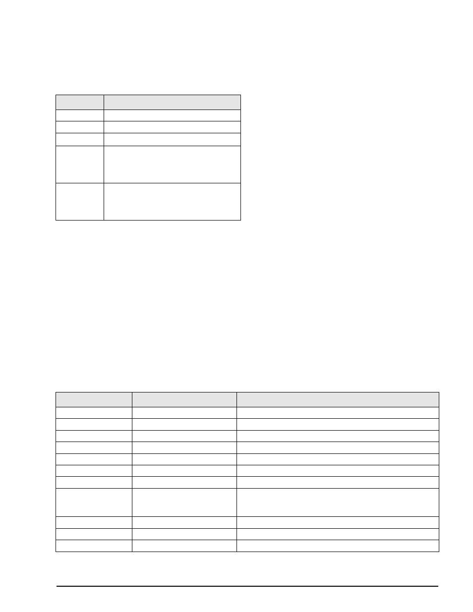
Reporting Commands
Reporting commands send speciÞc information to the
serial port. The commands listed in Table 9-2 can be
used in either setup mode and normal mode.
9.1.3
Clear and Reset Commands
The following commands can be used to clear and
reset the
920i
:
P C L R
: Program clear. Erases the loaded user
program (setup mode only).
RS
: Reset system. Resets the indicator without
resetting the conÞguration.
RESETCONFIGURATION
: Restores all conÞguration
parameters to their default values (setup mode
only). The
RESETCONFIGURATION
function can
also be initiated by pressing the
Reset Config
softkey under the VERSION menu.
NOTE:
All load cell calibration settings are lost when
the RESETCONFIGURATION command is run.
9.1.4
Parameter Setting Commands
Parameter setting commands allow you to display or
change the current value for a particular conÞguration
parameter (Tables 9-3 through 9-11).
Current conÞguration parameter settings can be
displayed in either setup mode or normal mode using
the following syntax:
command
Most parameter values can be changed in setup mode
only; setpoint parameters listed in Table 9-6 on
page 83 can be changed when in normal weighing
mode.
Use the following command syntax when changing
parameter values:
command=value
, where
value
is either a number or a parameter value. Use no spaces
before or after the equal (=) sign. If you type an
incorrect command, the display reads
??
.
For example, to set the motion band parameter on
Scale #1 to 5 divisions, type the following:
SC.MOTBAND#1=5D
For parameters with selectable values, enter the
command and equal sign followed by a question
mark:
command=?
to see a list of those values.
The indicator must be in setup mode to use this
function.
NOTE:
Some parameters are valid only if other
parameters or parameter values are specified. See the
configuration menus in Section
information about parameter dependencies. Restrictions
for front-panel configuration also apply to serial command
configuration.
Command
Function
DUMPALL
List all parameter values
SPDUMP
Print setpoint configuration
VERSION
Write
920i
software version
HARDWARE
Lists option cards installed in slots 1–14.
See Section 10.1.2 on page 94 for more
information about using the HARDWARE
command.
XE
Returns a10-digit code representing any
error conditions currently shown on the
front panel. See Section 10.1.4 on page 95
for more information.
Table 9-2. Reporting Commands
Command
Description
Values
SC.GRADS#n
Graduations
1–9999999
SC.ZTRKBND#n
Zero track band
OFF, 0.5D, 1D, 3D
SC.ZRANGE#n
Zero range
1.9%, 100%
SC.MOTBAND#n
Motion band
1D, 2D, 3D, 5D, 10D, 20D, OFF
SC.SSTIME#n
Standstill time
1-65535
SC.OVRLOAD#n
Overload
FS+2%, FS+1D, FS+9D, FS
SC.OVRTHR#n
Weighment threshold
SC.DIGFLTR1#n
SC.DIGFLTR2#n
SC.DIGFLTR3#n
Digital filtering
1, 2, 4, 8, 16, 32, 64, 128, 256
SC.DFSENS#n
Digital filter cutout sensitivity
2OUT, 4OUT, 8OT, 16OUT, 32OUT, 64OUT, 128OUT
SC.DFTHRH#n
Digital filter cutout threshold
NONE, 2D, 5D, 10D, 20D, 50D, 100D, 200D, 250D
SC.RATLTRAP#n
Rattletrap filtering
OFF, ON
Table 9-3. SCALES Serial Commands