2 load cells, 3 serial communications, Load cells – Rice Lake SURVIVOR LV Series Livestock Ring Scale User Manual
Page 12: Serial communications
8
590 AG Indicator Operators Manual
2.3.2
Load Cells
To attach cable from a load cell or junction box, remove connector J1 from the board. The connector plugs into a
header on the board. Connect cable from the load cell or junction box through the load cell cable cord grip to
connector J1 as shown in Table 2-1. If using 6-wire load cell cable (with sense wires), remove jumpers JP1 and JP2
before reinstalling connector J1 (see Figure ). For 4-wire installation, leave jumpers JP1 and JP2 on.
When connections are complete, reinstall connector J1 on the board.
Table 2-1. J1 Pin Assignments
J1 Pin
Function
1
+SIG
2
–SIG
3
+SENSE
4
–SENSE
5
SHIELD (see NOTE below)
6
+EXC
7
–EXC
Note
SHIELD wire connection is not used. Use grounding procedure described in Section 2.3.1.
For 6-wire connections, remove jumpers JP1 and JP2.
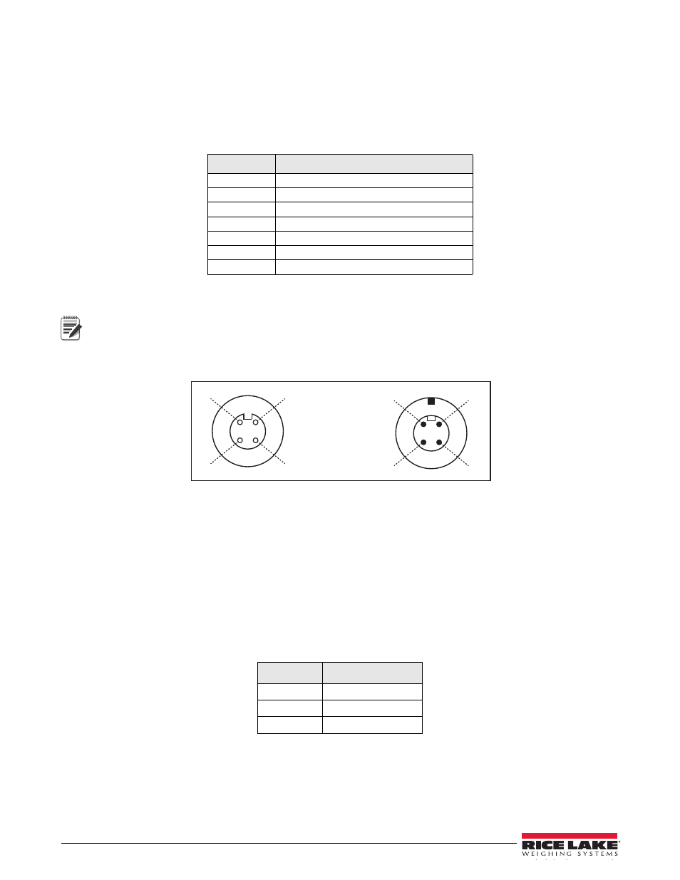
D
A
B
Indicator
A
D
C
B
Scale
A -EXC Black
B +SIG Green
C +EXC Red
D -SIG White
Connector
C
Figure 2-3. Scale/Indicator System Connection
2.3.3
Serial Communications
To attach serial communications cables, remove connector J2 from the board (see Figure 2-4). Connect
communications cable through cord grip to connector J2 as shown in Table 2-2.
Once cables are attached, reconnect J2 to the header on the board.
The 590 AG Indicator serial port supports full duplex RS-232 communications for connections to printers, PCs,
and other attached devices. See Section 3.0 for general configuration information; see Section 3.2.4 for serial port
configuration.
Table 2-2. J2 Pin Assignments
J2 Pin
Function
1
RS-232 TxD
2
RS-232 Ground
3
RS-232 RxD