0 installation, 1 unpacking and assembly, 2 enclosure disassembly – Rice Lake SURVIVOR LV Series Livestock Ring Scale User Manual
Page 10: 3 cable connections, Installation
6
590 AG Indicator Operators Manual
2.0
Installation
This section describes procedures for connecting load cell and serial communications cables to the indicator.
Instructions for battery and CPU board replacement are included, along with assembly drawings and parts lists for
the service technician.
WARNING
Use a wrist strap to ground yourself and protect components from electrostatic discharge (ESD) when
working inside the indicator enclosure.
2.1
Unpacking and Assembly
Immediately after unpacking, visually inspect the indicator to ensure all components are included and undamaged.
The shipping carton should contain the indicator with attached tilt stand, this manual and a parts kit. If any parts
were damaged in shipment, immediately notify Rice Lake Weighing Systems and the shipper.
The parts kit contains the items listed below:
•
Capacity, annunciator, and identification labels. The annunciator label (PN 53374) provides replacement
overlay decals for the displayed units annunciators.
•
3-position (PN 15888) and 7-position (PN 23165) pluggable terminal blocks for load cell and serial
communications connectors.
•
One 8-32 NC x 7/16 fillister head screw (PN 30623). This screw occupies the hole below the setup switch
access screw on the indicator backplate (see Figure 2-5).
•
Two 8-32 NC x 3/8 machine screws (PN 14862) for the indicator backplate (see #10 in Figure 2-3).
•
Five neoprene washers (PN 45042) for backplate screws included in the parts kit.
•
Four rubber bumpers (“feet”) for the tilt stand, PN 42149.
•
Two each of grounding clamps (PN 53075), external tooth lock washers (PN 15133), and kep nuts (PN
14676) for cable shield grounding against the backplate.
2.2
Enclosure Disassembly
The indicator enclosure must be opened to connect load cell and communications cables.
Power off the indicator and disconnect the AC adapter, if necessary. Place the indicator face-down on an antistatic
work mat. Remove the screws that hold the backplate to the enclosure body, then lift the backplate away from the
enclosure. Disconnect battery cable to connector J3, then set the backplate assembly aside.
2.3
Cable Connections
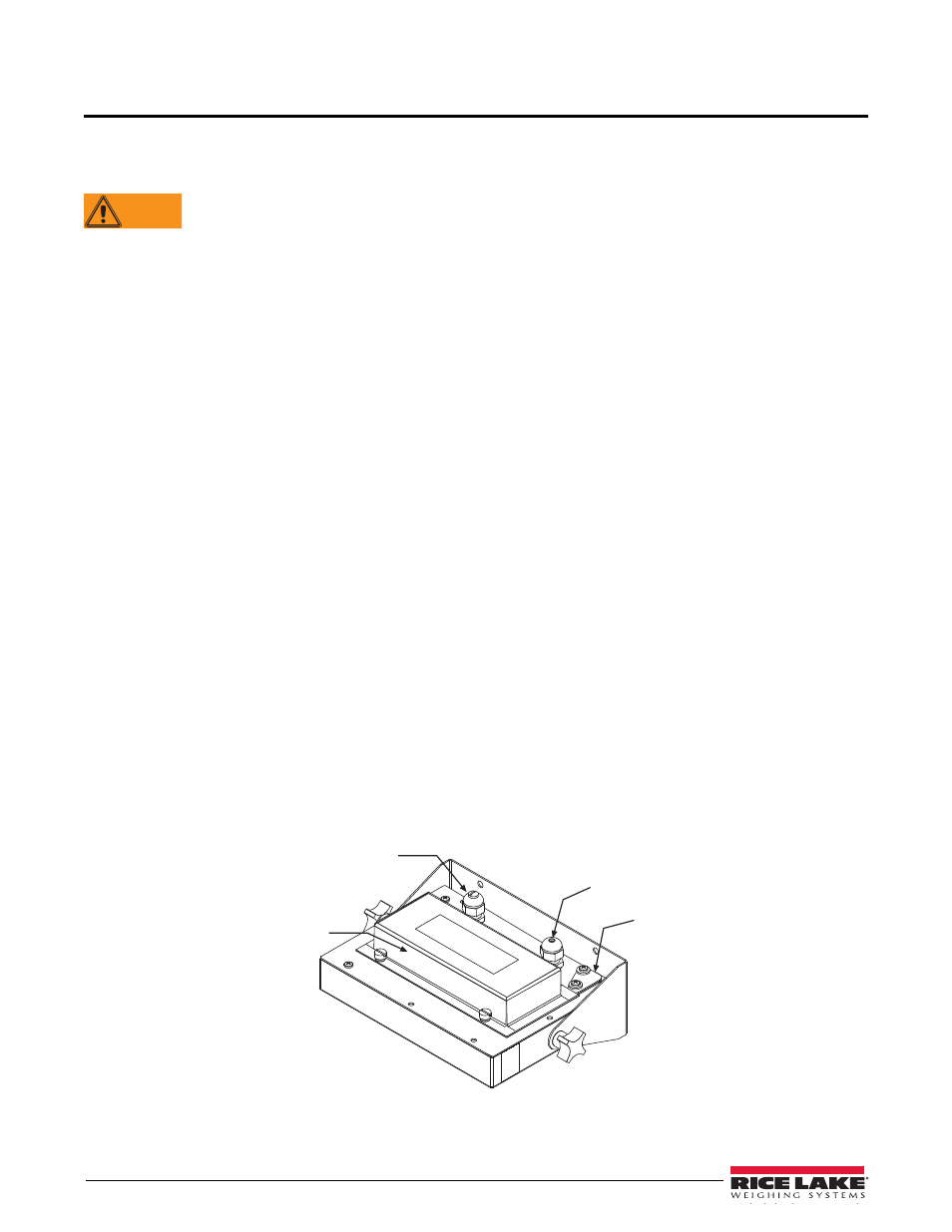
The 590 AG Indicator provides two cord grips for cabling into the indicator:
•
One for the load cell cable
•
One for serial communications.
Battery cover
Serial communications
cable cord grip
Load cell cable
cord grip
AC adapter
port cover
Figure 2-1. 590 AG Indicator Backplate, Showing Key Component Locations