0 installation, 1 unpacking and assembly, 2 enclosure disassembly – Rice Lake 420 Plus HMI Digital Weight Indicator Installation Manual User Manual
Page 10: 3 cable connections, Installation
6
420 Plus Installation Manual
2.0
Installation
This section describes procedures for connecting load
cells, digital inputs, and serial communications cables
to the
420 Plus
indicator. Instructions for field
i n s t a l l a t i o n o f t h e a n a l o g o u t p u t o p t i o n a nd
replacement of the CPU board are included, along with
assembly drawings and parts lists for the service
technician.
CAUTION
•
Use a wrist strap to ground yourself and protect
components from electrostatic discharge (ESD)
when working inside the indicator enclosure.
•
This unit uses line fusing which could create an
electric shock hazard. Procedures requiring work
inside the indicator must be performed by
qualified service personnel only.
•
The supply cord serves as the main power
disconnect for the
420 Plus
. The power outlet
supplying the indicator must be installed near the
unit and be easily accessible
2.1
Unpacking and Assembly
Immediately after unpacking, visually inspect the
420
Plus
to ensure all components are included and
undamaged. The shipping carton should contain the
indicator with attached tilt stand, this manual, and a
parts kit. If any parts were damaged in shipment, notify
Rice Lake Weighing Systems and the shipper
immediately.
The parts kit (PN 85219) contains the items listed
below:
•
Two, six-position screw terminals (PN 70599)
for connectors J4 & J1, two, three-position
screw terminals (PN 71125) for connectors J2
and J3, and one, four-position screw terminal
(PN 71126) for connector J6 (see figure 2-4).
•
Two 8-32NC x 7/16 fillister head screws (PN
30623).
•
Four 8-32NC x 3/8 machine screws (PN
14862) for the indicator backplate (see #1 in
•
Six neoprene washers (PN 45042) for
backplate screws included in the parts kit.
•
Four rubber bumpers (“feet”) for the tilt stand,
(PN 42149).
•
Three reducing glands (PN 15664).
•
One capacity label (PN 42350).
•
Three each of grounding clamps (PN 53075),
external tooth lock washers (PN 15133), and
k e p n u t s ( P N 1 4 6 2 6 ) f o r c a b l e s h i e l d
grounding against the enclosure.
•
One SEC C (section cap) and CLC
(Concentrated Load) (PN 85552) label.
•
Annunciator labels (PN 85555), replacement
overlay decals for labeling primary and
secondary units LEDs.
2.2
Enclosure Disassembly
The indicator enclosure must be opened to connect
cables for load cells, communications, digital inputs,
and analog output.
WARNING
The
420 Plus
has an on/off switch for the
load cells and processor functions. Before
opening the unit, ensure the power cord is
disconnected from the power outlet. The power outlet
must be located near the indicator to allow the operator to
easily disconnect power to the unit.
Ensure power to the indicator is disconnected, then
place the indicator face-down on an antistatic work
mat. Remove the screws that hold the backplate to the
enclosure body, then lift the backplate away from the
enclosure and set it aside.
2.3
Cable Connections
The
420 Plus
provides four cord grips for cabling into
the indicator: one for the power cord, three to
accommodate load cell, communications, digital
inputs, and analog output cables. Two of the three free
cord grips come with a plug installed to prevent
moisture from entering the enclosure. Depending on
your application, remove the plug from any cord grip
that will be used and install cables as required.
Note
The unit will keep the date and time as long as
it is plugged in, Even if display and load cells
are turned off. When the unit is unplugged, it
will lose date and time information.
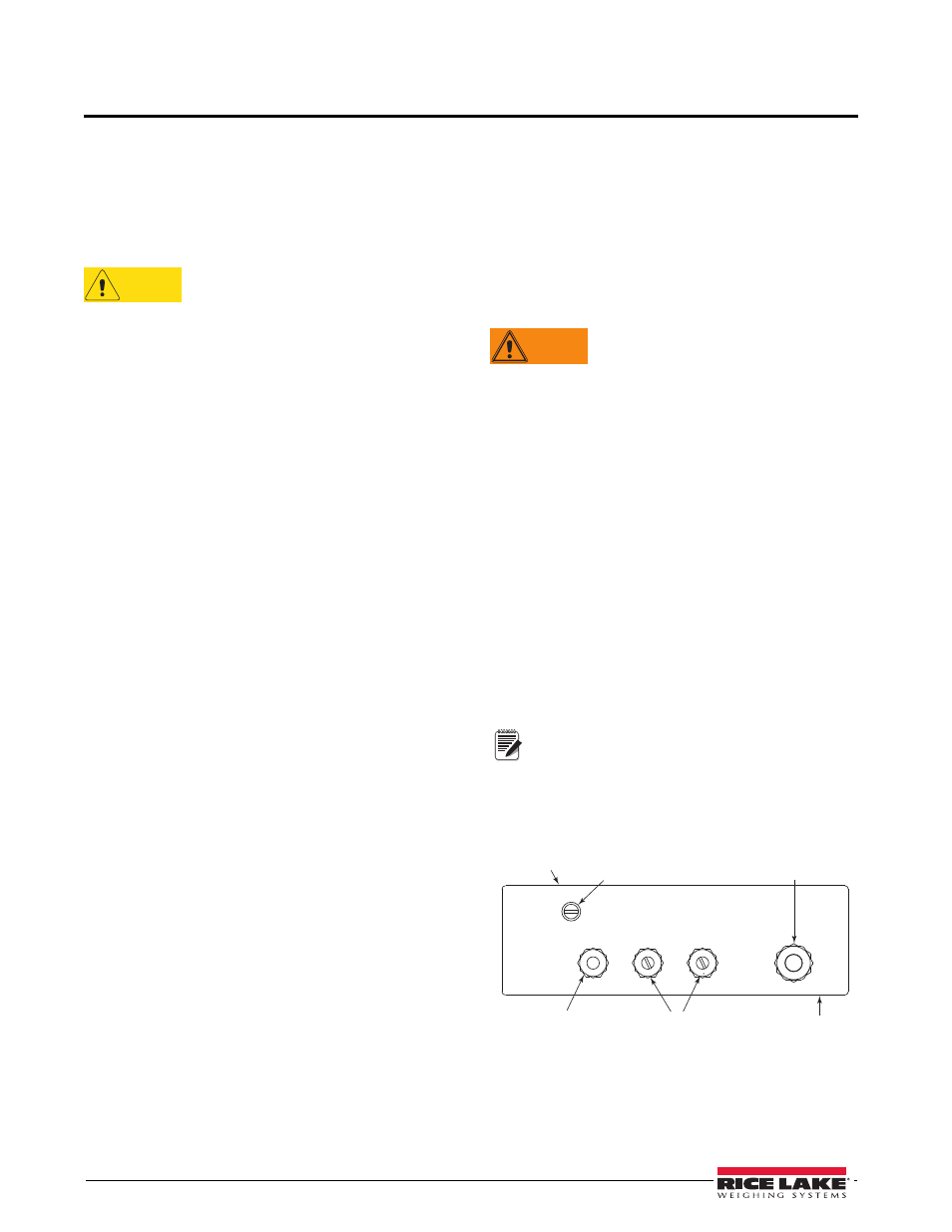
Figure 2-1 shows the recommended assignments for
the
420 Plus
cord grips.
Setup Switch
Access Screw
Communications Access
Cord Grip (Plugged)
Power Cord
Front of
Indicator
Backplate
Bottom View
Load Cell Cable
Cord Grip (Open)
Figure 2-1. Recommended Cord Grip Assignments