Head-sill-splicing-typeb – Oldcastle BuildingEnvelope ICR-225 User Manual
Page 26
23
March 2012
Phone: 1-866-OLDCASTLE (653-2278)
Web Address: www.oldcastlebe.com
I C R - 2 2 5 - I N S T A L L A T I O N M A N U A L
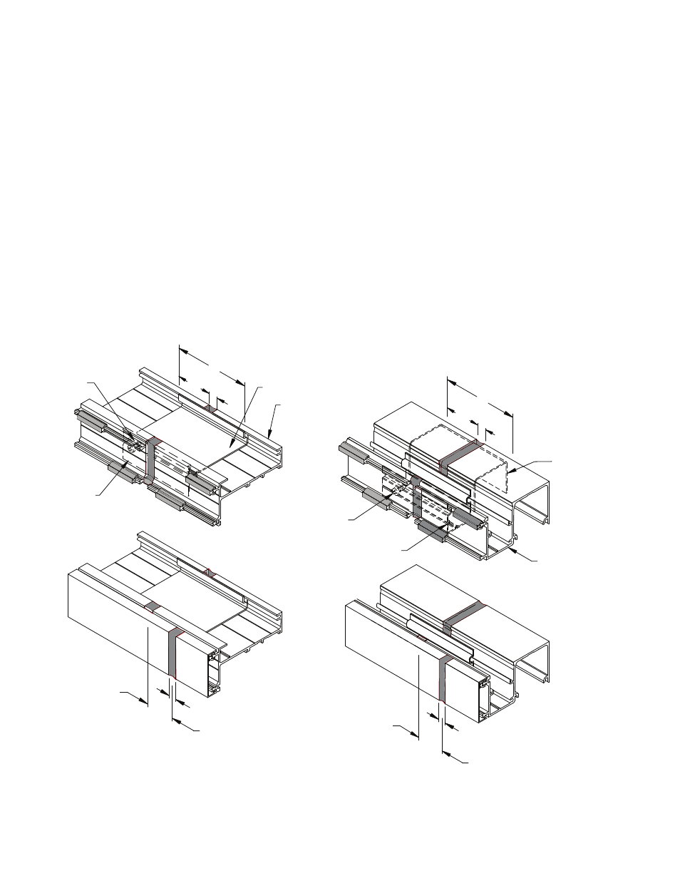
Figure 26
Head & Sill Member Splicing
ICR-120-01
3"
Head Splice
1/2"
Face Splice
Sill Splice
3"
ICR-117-01
FS-55
FS-55
ICR-119-01 (ICR-124-01)
ICR-451 (ICR-651)
Head
3"
Face Splice
1/2"
ICR-452 (ICR-652)
Sill
ICR-118-01
(ICR-123-01)
1/4"
1 1/2"
1/4"
1 1/2"
3”
FRAME SPLICING TYPE “B”
When the Frame Width exceeds 24’-0”, the head and sill members must be spliced. Locate splice joints at or
near mid-lite. Splice sill anchors 12” from the frame splice. Head and sill members should be cut to allow 1/4”
splice joint between each frame section. Sill anchors can be butted together
each side of the sill anchor joint.
7.1 Prior to setting frames in place, apply a non-hardening, non-skinning sealant to both sides of the splice
joint at the head and sill members. Attach splices to one side of frame with FS-55 (#10 x 1/2” Phillips
Pan Head) as shown in
FIGURE 26.
7.2 Place splice sleeves in head and sill of first frame section, slide the next frame section over the splice
sleeve to achieve a 1/4” joint.
SEE FIGURE 26.
7.3 Offset head and sill face cap splice joints by 3” from main member splices. Set joint at face caps at 1/2”
and seal as necessary.
7.4 Follow instructions for shimming and anchoring of frame.
7.5 Seal over gap at splice joint.