Head-sill-anchor-typeb – Oldcastle BuildingEnvelope ICR-225 User Manual
Page 24
21
March 2012
Phone: 1-866-OLDCASTLE (653-2278)
Web Address: www.oldcastlebe.com
I C R - 2 2 5 - I N S T A L L A T I O N M A N U A L
FRAME INSTALLATION TYPE “B”
6.1
Shim continuous sill anchor off floor. Anchor must be level.
SEE FIGURE 22 for shim placement.
Ends of sill anchor should be equal distance from wall on either side of opening. Refer to approved
shop drawing for anchor size and placement.
NOTE: Front of sill anchor is 2 3/16” (3 11/16”) in
front of rear edge of wall.
6.2
If optional reinforcing sleeves are used (6” system only), refer to Section B, page 29 for instructions
before proceeding. NOTE: Front edge of head anchor is 3 1/8” (4 5/8”) in front of rear edge
of frame. Slide head of frame over the head anchor which has been previously installed and rotate into
position, then lower onto sill anchor. Check to insure that frame is plumb, square and level. Check
caulk joints to insure uniformity.
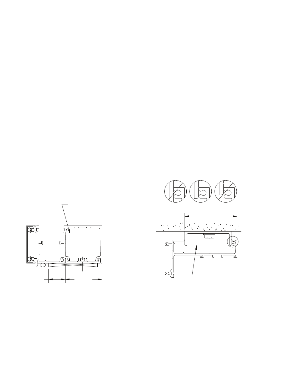
NOTE: For optimal performance of Head Anchor, die lines
must be visible on the anchor at the top of the frame. SEE FIGURE 23.
Head Anchor Position
Figure 23
CORRECT
3 1/8" (4 5/8")
Shim placement at Sill Anchor
1"
2 3/16"
(3 11/16")
Figure 22
See Figure 32, Page 31 for
optional Head reinforcing at
6” system
See Figure 32, Page 31
for optional Sill reinforcing
at 6” system