Frame-assembly-typea, Frame assembly type “a – Oldcastle BuildingEnvelope ICR-225 User Manual
Page 11
8
March 2012
Phone: 1-866-OLDCASTLE (653-2278)
Web Address: www.oldcastlebe.com
I C R - 2 2 5 - I N S T A L L A T I O N M A N U A L
2.3
2.2
2.1
Prior to applying sealant to any frame member, the aluminum must be cleaned. Consult sealant manufacturer
for cleaning recommendations. Steps 2.1 through 2.4 refer to screw spline assembly of system.
Refer to Step
2.5 for optional installation of shear block horizontals.
Attach ICR-112-01 mull caps using (2) FS-320 #10 U-Drive fasteners. Install and seal as shown in
FIGURE 8, page 9 . The attachment and sealing of the mull caps is one of the most critical phases of
the installation of the Type “A” assembly. Special care and attention should be given to this process.
Install ICW-12 isolator clips on all vertical and horizontal framing members at 12” O.C. Stagger the
clips by approximately 2” at the ends and 6” at intermediate clips.
SEE FIGURE 9, page 10. Once
clips are installed, snap face caps into position. The vertical caps should be installed first, then
horizontal, head and sill caps.
Seal ends of horizontal framing members before assembly.
SEE FIGURE 9, page 10.
If optional head reinforcing sleeves are used (6” system only), refer to Section B, page 29, for
instructions before proceeding.
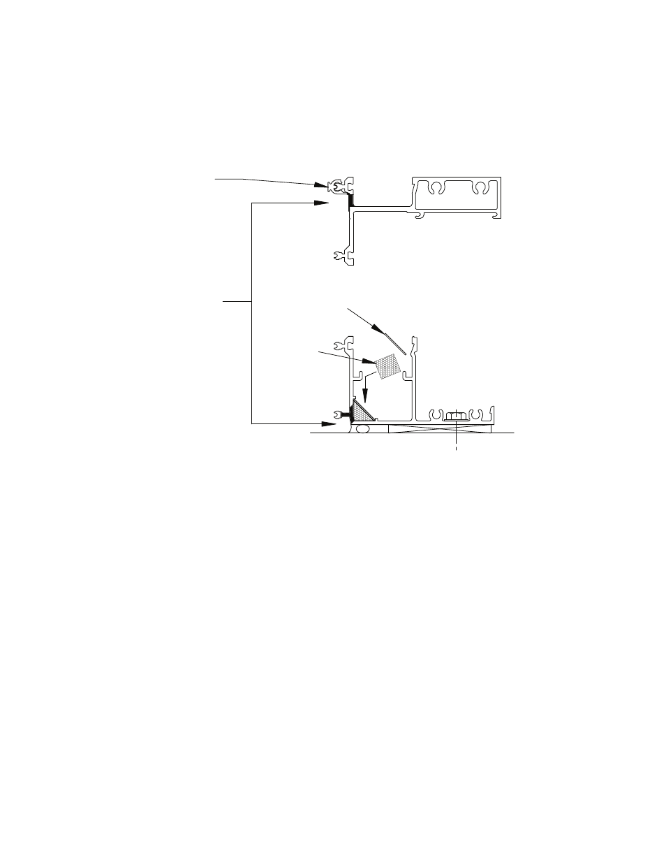
SPW- 295
Baffle
Retainer
HP- 1004
Baffle
Weep Holes
Figure 7
Horizontal
Sill
5/16” Dia. Weep Hole
ICR- 312 Baffle
clip @ Weeps
FRAME ASSEMBLY TYPE “A”