Frame-assembly-typea, Frame assembly type “a – Oldcastle BuildingEnvelope ICR-225 User Manual
Page 12
9
March 2012
Phone: 1-866-OLDCASTLE (653-2278)
Web Address: www.oldcastlebe.com
I C R - 2 2 5 - I N S T A L L A T I O N M A N U A L
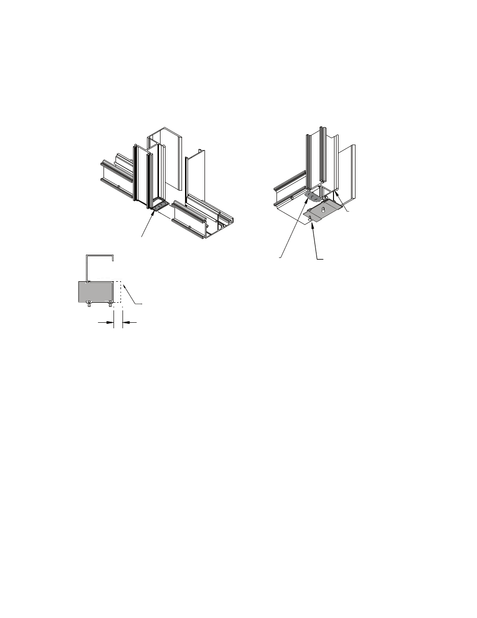
FRAME ASSEMBLY TYPE “A”
Apply bead of sealant
at Head and Sill
Tool sealant in glazing after installing
Mull Cap to insure proper seal
Apply sealant to
ends of Mullion
prior to installing
Mull Cap
Attach with (2)
FS-320 Drive Pins
Mull Cap Attachment
Figure 8
Modify ICR-112-01
Mull Cap
5/8"
Modify Mull Cap
as shown at Jamb
Apply generous bead of sealant
to Mull Cap at Head and Sill just
prior to assembly of units
2.4
Attach head, sill and intermediate horizontals to verticals with (2) FS-8 #14 x 1” Hex Head screws. DO
NOT OVER TORQUE SCREWS.
SEE FIGURE 9, page 10.
Optional shear block horizontals may be used with Type “A” installations. Begin by installing ICR-
180-01 (ICR-181-01) shear blocks to verticals using (2) FS-9 #14 x 1-1/2” Hex Head screws. Prior to
attaching horizontals to shear blocks apply sealant to face and top of shear block and along front edge
of vertical in line with face of horizontal. Roll the horizontal over the shear block and attach with (1)
FS-55 #10 x ½” Phillips Round Head screw.
SEE FIGURE 21, page 20.
2.5