Frame-iinstallation-typea – Oldcastle BuildingEnvelope ICR-225 User Manual
Page 14
11
March 2012
Phone: 1-866-OLDCASTLE (653-2278)
Web Address: www.oldcastlebe.com
I C R - 2 2 5 - I N S T A L L A T I O N M A N U A L
FRAME INSTALLATION TYPE “A”
3.1
Install frame sections starting with a frame unit comprised of a jamb and vertical mullion with head/sill
and horizontals. Each additional frame unit will be made from mullion filler and a mullion until you
reach the opposite end of the opening. The final frame member will be made from the mullion filler and
a jamb. (This description assumes a ribbon installation with a jamb at each end. Your installation may
vary.)
A.
B.
C.
D.
Each frame unit will be assembled and sealed as shown in
FIGURE 8, page 9 and FIGURE 9,
page 10 with mullion caps installed as shown in FIGURE 8, page 9 . A second bead of sealant is
applied to the face cap that is protruding into the opening just prior to assembly of the frame units.
SEE FIGURE 8, page 9. NOTE: Sealant must be tooled at head and sill to insure proper
seal.
When installing each unit, first slide head member over the head anchor, which has been
previously installed, and rotate unit into position. Each adjacent unit will be rotated into position,
between the mull caps at the head and sill, and snapped into position. (A furniture clamp may
be use to simplify the snapping of units together.)
NOTE: When optional head reinforcing
sleeves are used (6” system only), slide head member into position over head anchor so
that reinforcing sleeve is centered on head anchor.
Make sure each unit is plumb, square and level, anchoring each unit as it is installed
.
Once all units are installed inspect caulk joints to insure uniformity.
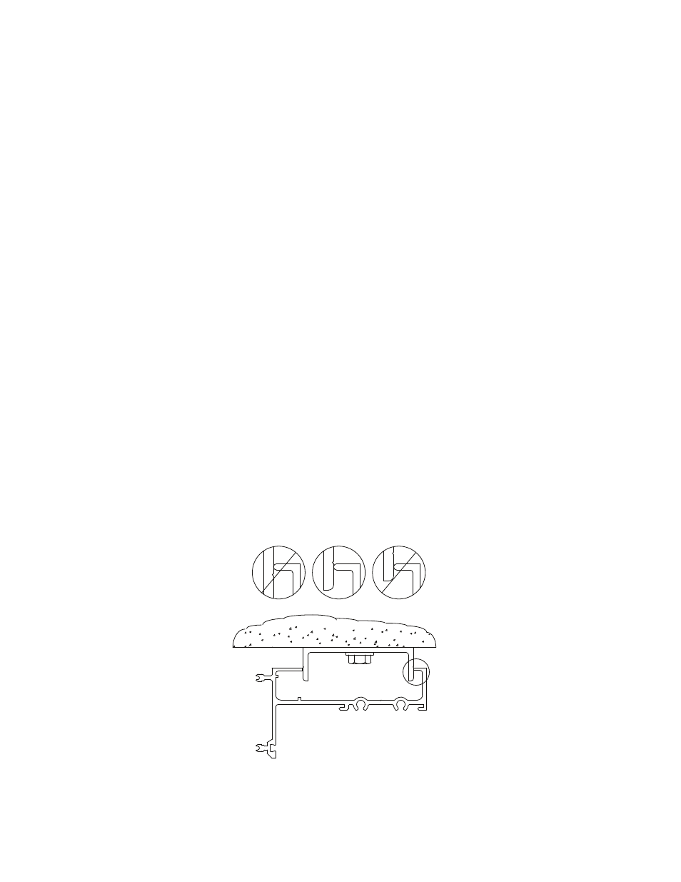
NOTE: For optimal performance of Head Anchor, Die Lines must be visible on the Anchor at the top of
the Frame. SEE FIGURE 10 below.
Figure 10
Head Anchor Position
CORRECT