Adjusting the brake linkage – Losi LOSB0083 User Manual
Page 3
Adjusting the Brake Linkage
1. With the throttle in the neutral position, adjust the brake
linkage rods as shown. Note the amount of thread showing on
each brake rod.(Fig. 9)
The brake portion of the linkage adjustment is now complete. Do NOT proceed if the above test
does not work, repeat the procedure if necessary.
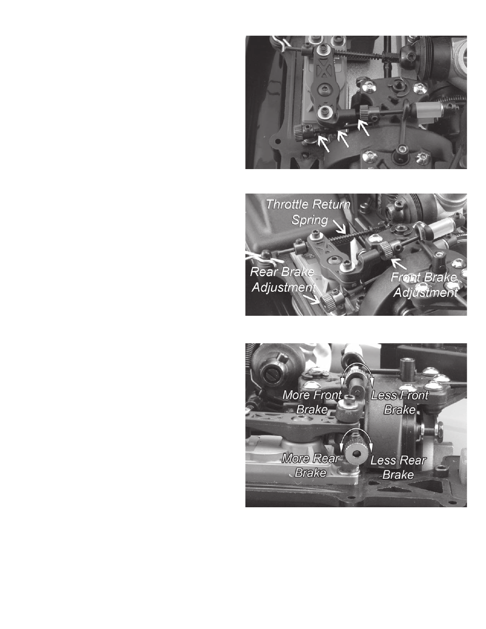
2. Slide the collar (black) along the front brake rod (upper)
towards the fuel tubing, until there is no play left in the link-
age. The fuel tubing should NOT be compressed. Repeat this
process for the rear brake rod (lower).
NOTE: The upper adjustment rod is for the front brake and the
lower for the rear brake (Fig. 10).
3. At the end of this adjustment process, the brakes should
NOT apply any resistance at the neutral throttle position.
From adjustment in step 2, the brakes may be applying some
resistance which can be felt by rotating the spur gear by hand
through the bottom of the chassis. To ensure there is no resis-
tance, rotate each of the adjustment knobs (blue) one turn in
the clockwise direction (Fig. 11)
4. Check the adjustment, apply full throttle and return to neutral
and check the brakes for resistance. Repeat a couple times
and check for consistent operation.
5. Watch the brake linkage as the transmitter trigger is slowly
moved to the full brake position. Adjust the brake EPA of the
transmitter so that when full brake is applied the spur gear is
diffi cult to turn by hand. The brake EPA can be adjusted later to
get the desired amount of brake for various driving conditions.
8. Before proceeding, move the trigger to the full brake posi-
tion and check the throttle return spring to ensure that it is not
compressed completely.
NOTE: If the throttle return spring is fully compressed, the
most probably cause is either the throttle servo arm is installed
improperly or the EPA is set too high. Proper adjustement
should allow for at least .250” (6.5mm) of additional movement
in the full brake position.
Fig. 10
Fig. 11
Fig. 9