Vmp1 configuration – Kontron VMP1 User Manual
Page 64
VMP1
Configuration
ID 19972, Rev. 0101
Page 4 - 18
® PEP Modular Computers GmbH
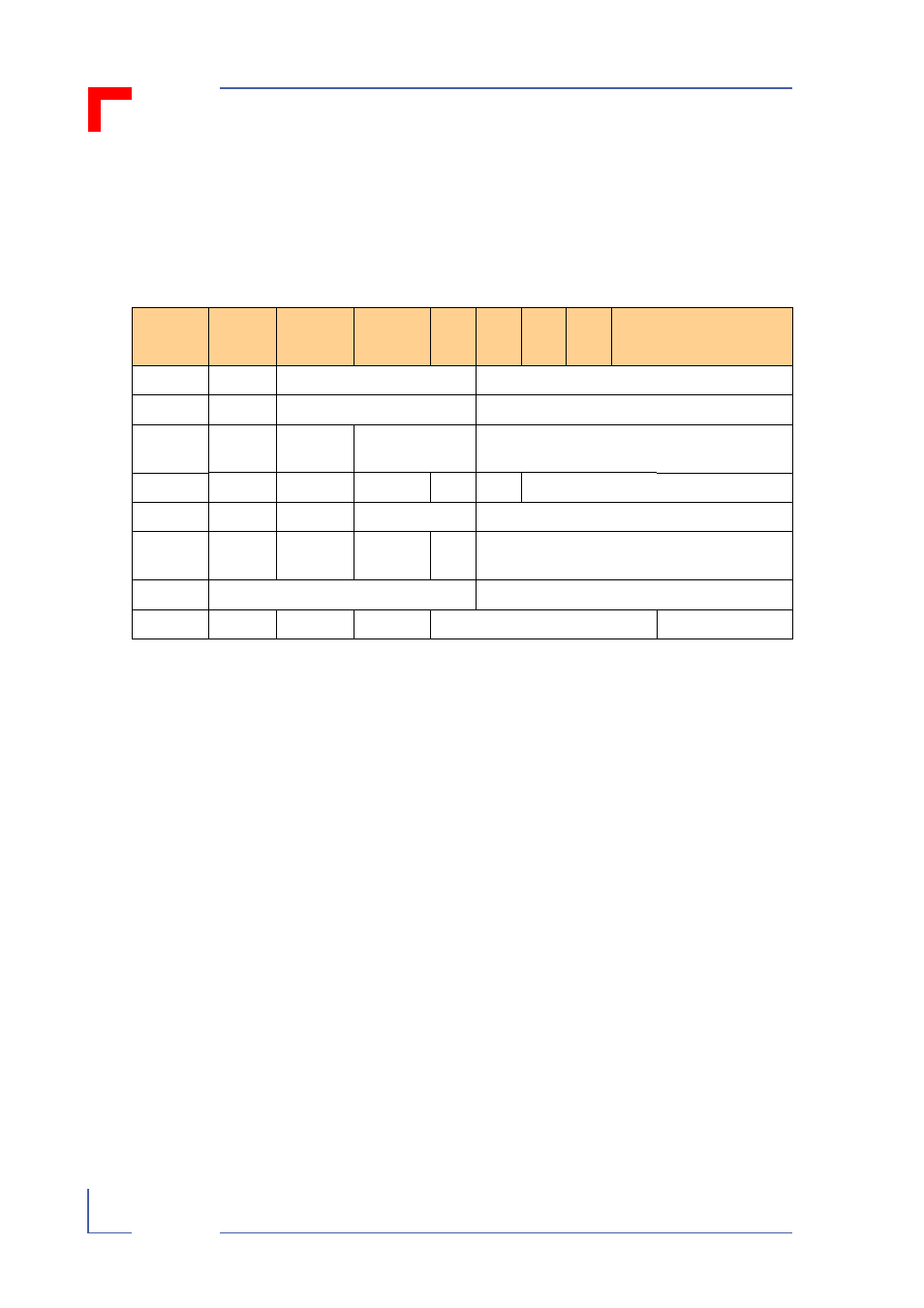
4.3.6
Real-time Clock
Access to the RTC is effected via the I2C bus. The RTC uses address 0xD0
For more detailed information please refer to the manuals for the
ST - Microelectronics M41T56 and the Motorola MPC 8240 (I2C - Bus).
Meanings of abbreviations in Table 4-24
Table 4-24: Register Map RTC M41T56
Address
D7
D6
D5
D4
D3
D2
D1
D0
Function/Range
in BCD Format
0
ST
10 Seconds
Seconds
Seconds / 00-59
1
X
10 Minutes
Minutes
Minutes / 00-59
2
CEB
CB
10 Hours
Hours
Century 0-1/Hour
00-23
3
X
X
X
X
X
Day
Day / 00-07
4
X
X
10 Date
Date
Date / 01-31
5
X
X
X
10
M.
Month
Month / 01-12
6
10 Years
Years
Year / 00-99
7
OUT
FT
S
Calibraton
Control
CEB
= Century enable bit
CB
= Century bit
FT
= Frequency test bit
OUT
= Output level
ST
= Stop bit
S
= Sign bit
$
$
Note:
When the RTC has once been stopped due to low voltage, it is
necessary to re-initialize the “Seconds” “Minutes” and “Hours” reg-
isters before it will run again.
- CP3003-SA uEFI BIOS (72 pages)
- CP3003-SA (36 pages)
- CP3002 (38 pages)
- CP3002-RC uEFI (64 pages)
- CP-RIO3-05 (42 pages)
- CP3002-RC (30 pages)
- CP342 (52 pages)
- CP930 (46 pages)
- CP932 (52 pages)
- CP346 (72 pages)
- CP384 (66 pages)
- CP383 (74 pages)
- CP382 (58 pages)
- CP381 (60 pages)
- CP372 (64 pages)
- CP371 (60 pages)
- CP-RIO3-04S (38 pages)
- CP390 (36 pages)
- CPS3410 (9 pages)
- CPS3402 (9 pages)
- CPS3105 (9 pages)
- CPS3101 (9 pages)
- CPS3003-SA (19 pages)
- PB-SIO4 (34 pages)
- PB-SIO4A (34 pages)
- PB-DOUT8 (34 pages)
- VMOD-2 (82 pages)
- VSBC-32 (110 pages)
- VM42 (62 pages)
- Bootstrap Loader (24 pages)
- VMP1 with Netbootloader (120 pages)
- NetBootLoader (86 pages)
- VMP2 (142 pages)
- VMP3 (154 pages)
- CP-RIO6-923 (32 pages)
- CP-RIO6-923-F (32 pages)
- CP-RIO6-001 (28 pages)
- CP-RIO6-001-HD-VGA (46 pages)
- CP-RIO6-M (20 pages)
- CP-RIO6-B (28 pages)
- CP6925 (42 pages)
- CP6002 uEFI BIOS (76 pages)
- CP6002 IPMI (40 pages)
- CP6002 (42 pages)