Configuration, Vmp1 configuration – Kontron VMP1 User Manual
Page 49
VMP1
Configuration
ID 19972, Rev. 0101
Page 4 - 3
® PEP Modular Computers GmbH
4. Configuration
4.1 Jumper Settings
Please see Figures 2-3 and 2-4 in Chapter 2 to view the positions of the jumpers and
resistors on the board.
4.1.1
Bootstrap Loader / Socket Jumper J1
The Jumper J1 is used to select the memory position from which the VMP1 fetches its
boot code. It determines the address position of the onboard Flash window and the
Flash/SRAM expansion socket (DIL600, 32-pin).
Note: The MPC8240 initially fetches its boot code from address 0xFFF0 0100!
4.1.2
RTC (Real-time clock) Calibration Output J2
Frequency test output is used for calibration of the onboard RTC. The RTC provides a
512 Hz frequency test signal for calibration purposes. Please refer to the datasheet of
the ST M41T56 for detailed information (for position of J2 on the board please see figure
2-3).
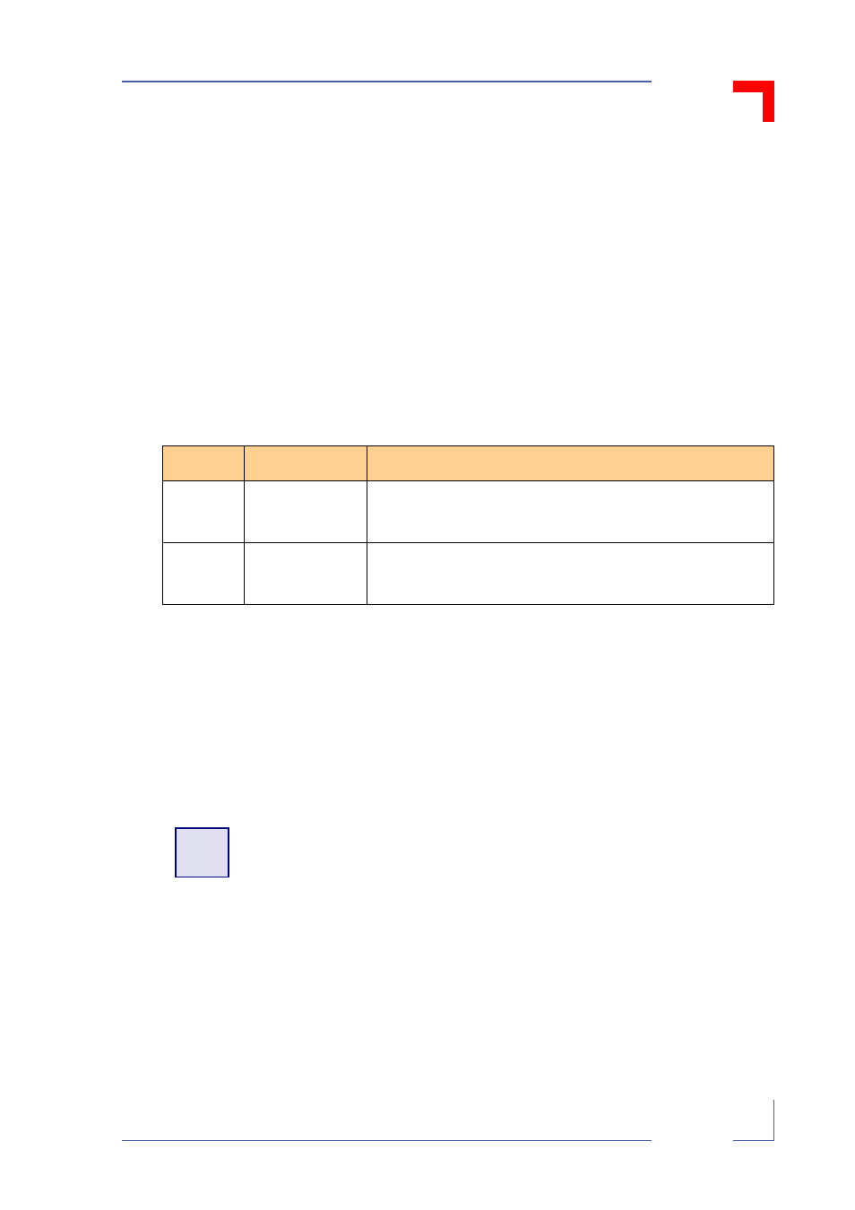
Table 4-1: Bootstrap Loader / Socket Jumper J1 Settings
J1
Meaning
Address Assignment
Open
VMP1 fetches
boot code from
onboard Flash
Socket:
0xFFF8 0000 - 0xFFFF FFFF
Onboard Flash window:
0xFFF0 0000 - 0xFFF7 FFFF
Closed
VMP1 fetches
boot code from
socket
Socket:
0xFFF0 0000 - 0xFFF7 FFFF
Onboard Flash window:
0xFFF8 0000 - 0xFFFF FFFF
!
Warning!
J2 must not be bridged.