Vmp1 introduction, 3 vmp1 main specifications – Kontron VMP1 User Manual
Page 20
VMP1
Introduction
ID 19972, Rev. 0101
Page 1 - 6
® PEP Modular Computers GmbH
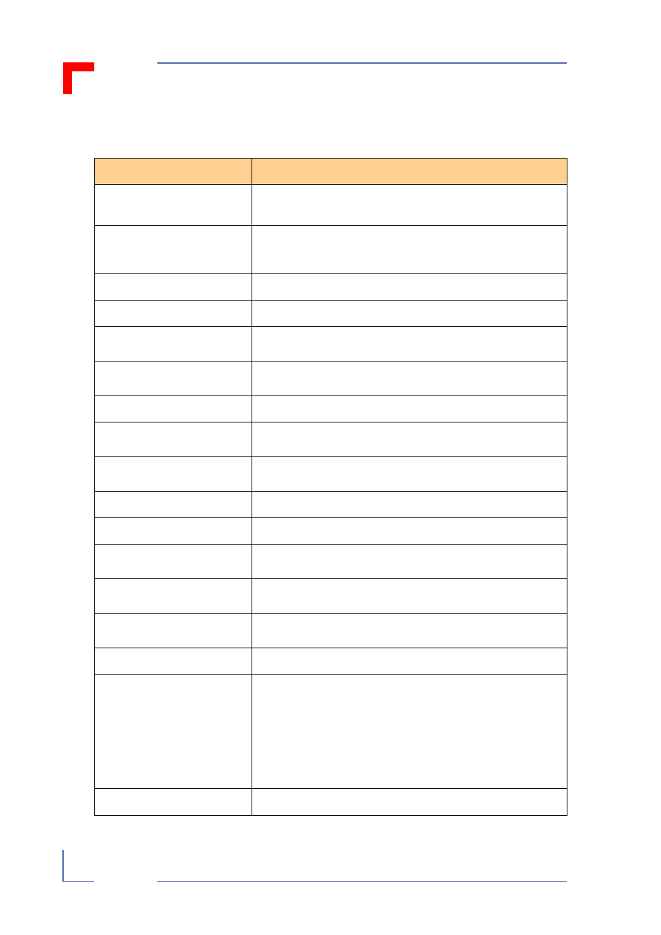
1.3 VMP1 Main Specifications
Table 1-1: VMP1 Main Specifications
VMP1
Specifications
Operating System
Support
Initial boot loader with capability to load VxWorks and other
Real-time operating systems
VME Interface
ANSI/VITA 1-1994 for VME, approved April 10, 1995
Support for A24: D16/D8 master and A24: D16/D8 slave
interface
Processor
Motorola MPC8240 with integrated PCI interface 250MHz
Boot Device
8 MB Flash for bootloader and ROMable OS / Socket
Main Memory
32 MB or 64 MB of onboard SDRAM with ECC support
available as standard (128 MB available on request)
Cache Structure
16K, 32 byte line, 4-way set associative instruction cache
16K, 32 byte line, 4-way set associative data cache
Flash
8 MB on-board Flash (soldered)
DIL600 Socket
Socket for Flash extension by another 512 kB or addition of
Flash disk (M-System) with up to 144 MB
PCI Expansion Connector
1 x Samtec SMT Board-to-Board connector 100-pin
order number: FLE - 15 - 01 - G - DV
Ethernet
10Base-T / 100Base-TX
SRAM
256 or 512 kB NV SRAM on the DIL600 socket
Serial Port
16550 compatible Dual UART; 2 x RS-232 or
1 x RS232 + 1 x RS485
Watchdog
Watchdog generates Exception Condition / Reset or NMI
(software configurable)
RTC
backed up with GoldCap / Data retention for about 5 days /
backup battery possible
EEPROM
1 x 24LC16 for special purposes (8x256Byte)
LED’s
6 LED’s:
red = general purpose
yellow = watchdog active
green = general purpose
green = Ethernet Link Integrity,
green = Ethernet Activity
green = Ethernet Speed
Switches
Two push-buttons (Reset and Abort)