Vmp1 configuration, 3 onboard device addresses – Kontron VMP1 User Manual
Page 55
VMP1
Configuration
ID 19972, Rev. 0101
Page 4 - 9
® PEP Modular Computers GmbH
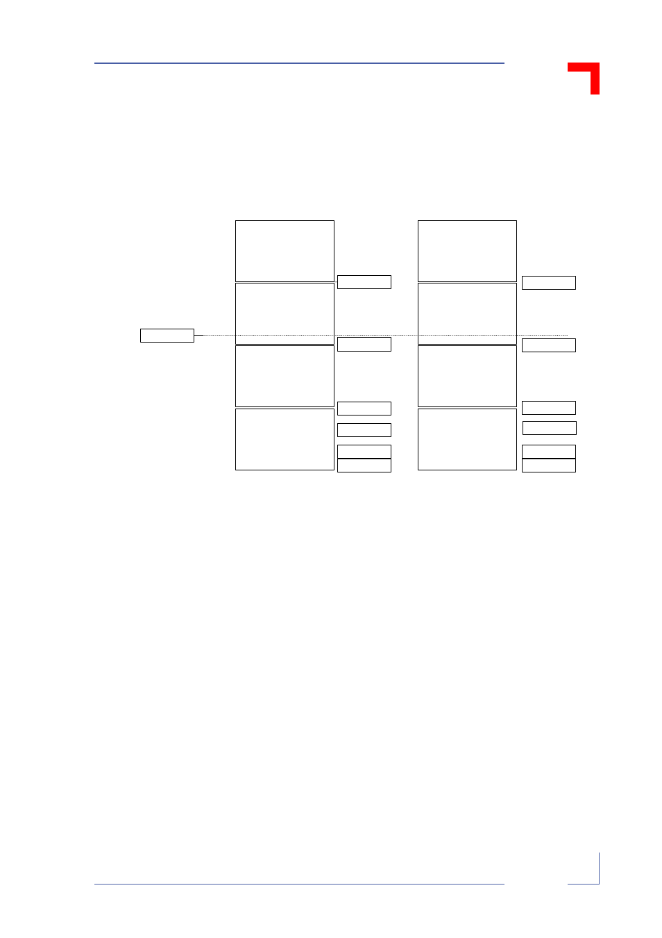
4.3.3
Onboard Device Addresses
Figure 4-3: VMP1 Device Address Map
$
$
Note:
•
For write access to this address area (0xFFE0 0000-0xFFFF
FFFF), it is only possible to use byte-wide write commands.
•
When the memory expansion socket is used for NVSRAM, byte
0xFFF0 0000 (J1 installed) or byte 0xFFF8 0000 (J1 removed)
is reserved for the output of post codes to the VMP1-Post. Data
should not be stored at either of these locations.
UART A
UART B
Onboard Register
+
Onboard Register
+
UART B
UART A
reserved
reserved
Socket
Socket
soldered FLASH,
(512k page)
soldered FLASH,
(512k page)
Reset Entry
Boot jumper J1 installed
Boot jumper J1 removed
0xFFF8 0000
0xFFF0 0000
0xFFE8 0000
0xFFE0 0010
0xFFE0 0008
0xFFE0 0000
0xFFF8 0000
0xFFF0 0000
0xFFE8 0000
0xFFE0 0010
0xFFE0 0008
0xFFE0 0000
0xFFFF 0100
- CP3003-SA uEFI BIOS (72 pages)
- CP3003-SA (36 pages)
- CP3002 (38 pages)
- CP3002-RC uEFI (64 pages)
- CP-RIO3-05 (42 pages)
- CP3002-RC (30 pages)
- CP342 (52 pages)
- CP930 (46 pages)
- CP932 (52 pages)
- CP346 (72 pages)
- CP384 (66 pages)
- CP383 (74 pages)
- CP382 (58 pages)
- CP381 (60 pages)
- CP372 (64 pages)
- CP371 (60 pages)
- CP-RIO3-04S (38 pages)
- CP390 (36 pages)
- CPS3410 (9 pages)
- CPS3402 (9 pages)
- CPS3105 (9 pages)
- CPS3101 (9 pages)
- CPS3003-SA (19 pages)
- PB-SIO4 (34 pages)
- PB-SIO4A (34 pages)
- PB-DOUT8 (34 pages)
- VMOD-2 (82 pages)
- VSBC-32 (110 pages)
- VM42 (62 pages)
- Bootstrap Loader (24 pages)
- VMP1 with Netbootloader (120 pages)
- NetBootLoader (86 pages)
- VMP2 (142 pages)
- VMP3 (154 pages)
- CP-RIO6-923 (32 pages)
- CP-RIO6-923-F (32 pages)
- CP-RIO6-001 (28 pages)
- CP-RIO6-001-HD-VGA (46 pages)
- CP-RIO6-M (20 pages)
- CP-RIO6-B (28 pages)
- CP6925 (42 pages)
- CP6002 uEFI BIOS (76 pages)
- CP6002 IPMI (40 pages)
- CP6002 (42 pages)